


This is an official troubleshooting and repair guide for AvalonMiner 7 and AvalonMiner 8 series.
In this guide, you will see how to disassemble and separate all miner components. In addition, it will help you to replace a faulty miner component like a broken cooling fan or faulty PCB board.
You will also learn how to make the fault diagnosis to your miner in a case of a miner malfunction and how to find out which miner component is most likely not working correctly.
This guide is made using an AvalonMiner 841 unit, but the same principles apply to other compatible models mentioned in this guide.
I. General information, most common tools needed
Most common tools needed:
• Portable electric screwdriver (it is good to have both PH1 and PH2 size screwdrivers/tips)
• Digital multimeter: fluke 15b+
• Static electricity protection (ESD mat or anti static wrist strap)
• If you don’t have anything for static electricity protection, please at least ground yourself by touching a grounded object to discharge the static electricity before touching a PCB board
• Good quality Antminer thermosetting adhesive
• Pure isopropyl alcohol for cleaning the old Antminer thermosetting adhesive
• Soft cloth or soft paper for cleaning the old Antminer thermosetting adhesive
These instructions apply to following AvalonMiner 7 and 8 series models:
• AvalonMiner 721
• AvalonMiner 741
• AvalonMiner 761 (with a built-in power supply unit)
• AvalonMiner 821
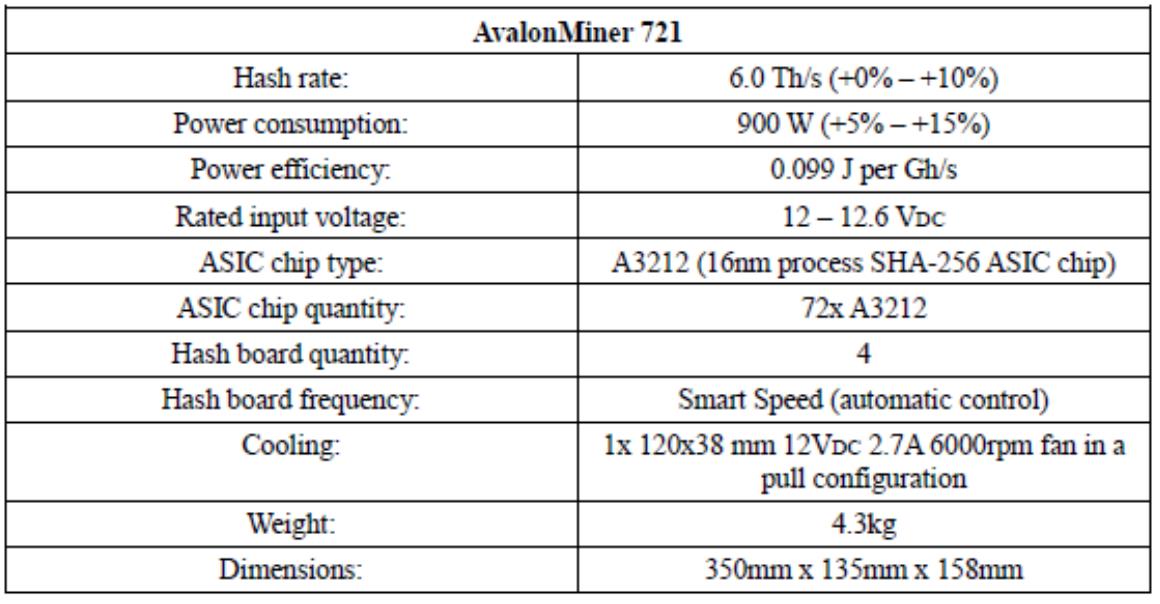
AvalonMiner 721 technical specifications.
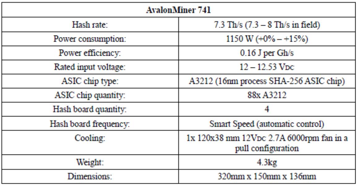 AvalonMiner 741 technical specifications.
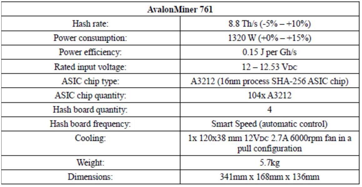 AvalonMiner 761 technical specifications.
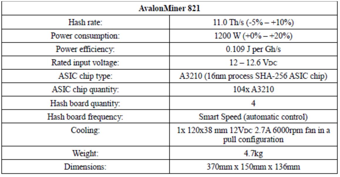 AvalonMiner 821 technical specifications.
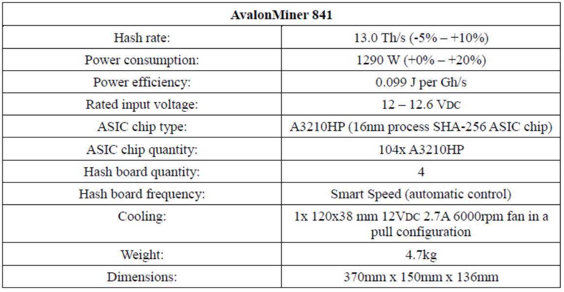
AvalonMiner 841 technical specifications.
II. Troubleshooting
In this chapter, you will see the common methods for the troubleshooting process, and you will also see example cases about the most common issues.
The goal is to help understand how to determine which miner component is causing the miner operation malfunction.
1. How to indicate your miner’s physical location
You can use the indicator LED to help you locate the miner.
Press the indicator LED switch button to change the state from ‘LED OFF’ to ‘LED ON.’
You can find the indicator LED switch button location by following these steps:
1) Go to the controller web configuration page by using your web browser and log in.
2) Click ‘Advanced Version’ to access the advanced user features in the OpenWrt firmware.
3) Click ‘CGMiner Status’ to see the status for all the devices connected to the controller.
4) Choose the AvalonMiner unit you would like to locate and click the ‘LED OFF’ button located in the Indicator field. Now you should see that status change into ‘LED ON.’ Further observations about this situation are shown in two figures below.
 Normal miner operation before pressing the indicator LED button - the indicator LED color is blue.
 After pressing the indicator LED button the miner in question changes the indicator LED color to white.
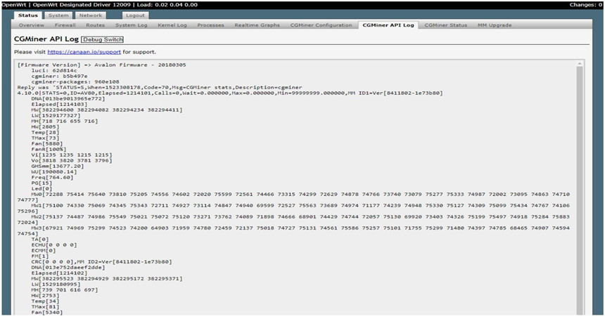
The following instructions will tell you how to locate and open the CGMiner API Log.
By reading the log text, you can see lots of technical information related to the miner's performance.
Step 1: Use your web browser and access the controller web configuration page.
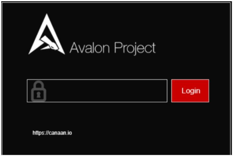
Step 2: Click ‘Advanced Version’ to access all user features.
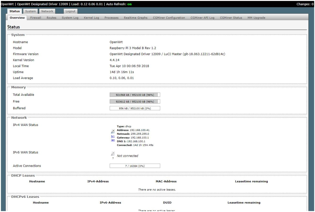
 Step 3: You are now able to see all the features available.
Now you need to click ‘CGMiner API Log’ to access the log text.
 Step 4: Click 'Debug Switch'. After that, you are ready to read and examine the CGMiner API Log.
2. Information about indicator LED colors and CGMiner API Log error codes
During the troubleshooting, it is best to find and use all the information available so that the repair is a quick and straightforward process.
The miner can report a specific issue with different LED colors and error codes.
In the following tables, you can see a description for each LED color and error code.
Please remember to click the ‘Debug Switch’ button before reading and examining the CGMiner API Log.
AvalonMiner LED colors.
AvalonMiner LED colors | |
LED status | Description |
White | Power on. |
Blue | Working normally. |
Yellow | Idle normally. |
Green | Detect cooling fan and MCU board. |
White blinking or constant white | Turn on LED manually. |
Red | Toohot/Loopback failed/PG failed/Core test failed/Voltage error/Temperature sensor error/No fan. |
PMU board LED colors.
PMU board LED colors | |
LED status | Description |
Green | Power ok. |
Red | Power is not good. |
No LED light | Usually means that the PMU board is faulty. |
AUC3 Converter LED colors.
AUC3 Converter LED colors | |
LED status | Description |
Blue | Initializing or idle normally. |
Green | Working normally. |
Red | Communication failed or rejected share (if the LED blinks shortly) |
One of the most frequent errors is the socket connect error.
Socket connect failed => Connection refused
This error can happen because of numerous different things, but a list shows a few of them.
• Miner is still in the startup process
• Incorrect pool settings
• Wrong OpenWrt firmware version
• Communication error.
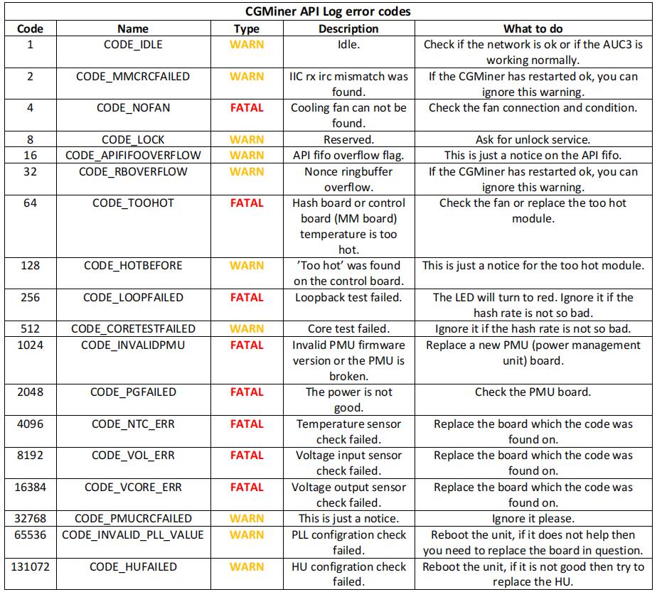
WARN: It designates potentially harmful situations, but you can ignore them.
FATAL: It designates very severe error events that will presumably lead the AvalonMiner to crash.
• Wrong OpenWrt firmware version
• Communication error.
3. How to read the abbreviations and values found in the CGMiner API Log
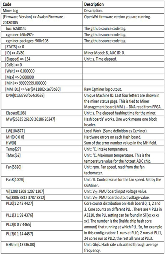
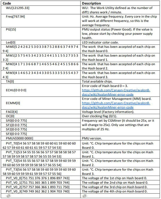
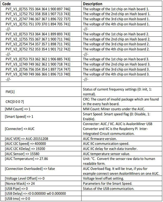
In this following table, you can see the CGMiner API Log thoroughly explained, row by row.
This provides you a lot of help in the troubleshooting process, as you can determine possible issues based on the values seen in the CGMiner API Log. The information is divided into three parts.
List of codes found in the CGMiner API Log. Part 1.
List of codes found in the CGMiner API Log. Part 2.
List of codes found in the CGMiner API Log. Part 3.
4. How to check the power supply unit health
If you want to know if the power supply is passing any voltage to the PMU board, you can measure the +12V rail output voltage to find out.
According to the ATX specification, the measured voltage should be from 11.4 to 12.6 VDC. Please also take into account the rated input voltage for your AvalonMiner. The safest area for the input voltage is 12.0 to 12.5 VDC.
For measuring the voltage, you need a multimeter.
You can easily measure the voltage by applying one multimeter test lead to the +12V (yellow) and one multimeter Fluke 15b+ test lead to the COM (black).
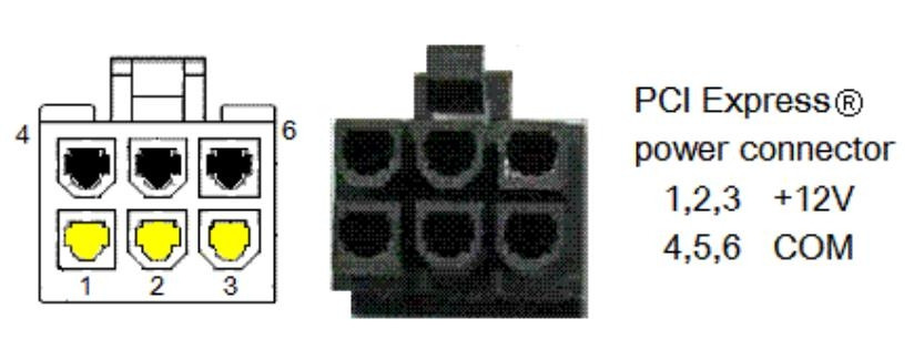
First, you need to select the correct measuring mode by using the selection knob in the middle of the multimeter. Make sure that your test leads are connected correctly to the multimeter for the voltage measurement setup.
You can use any safe methods, tools, or tape you need to hold the power connector still so that it is easy for you to hold the test leads safely in position.
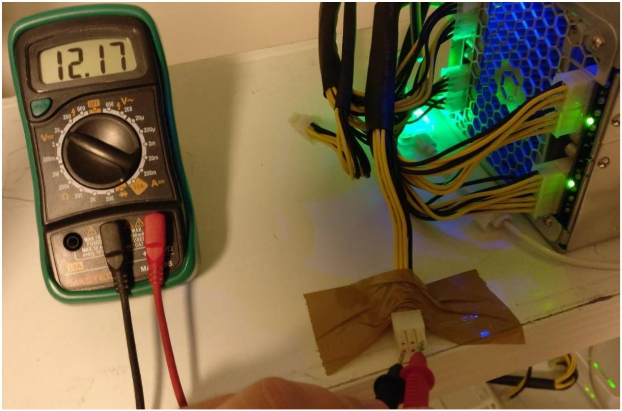 5. Cooling fan troubleshooting
If your miner won’t start operating, one of the first things to check if the cooling fan is working. You can check it by doing both visual inspection and looking at the miner status page.
If you find a miner with a fan reading at 0 rpm or close to it, then it is pretty clear that you need to replace that miner’s cooling fan.
Please also see any indicator LED colors or log error codes related to a cooling fan issue.
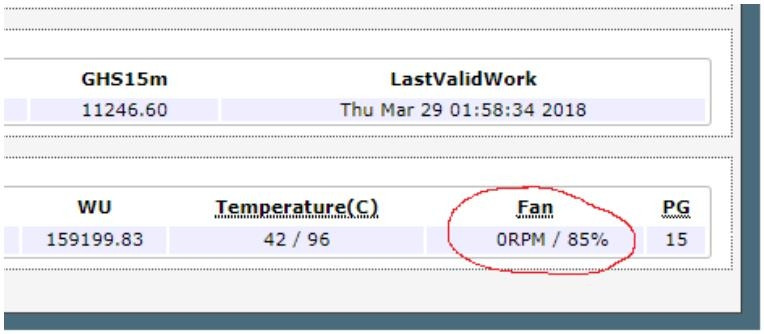
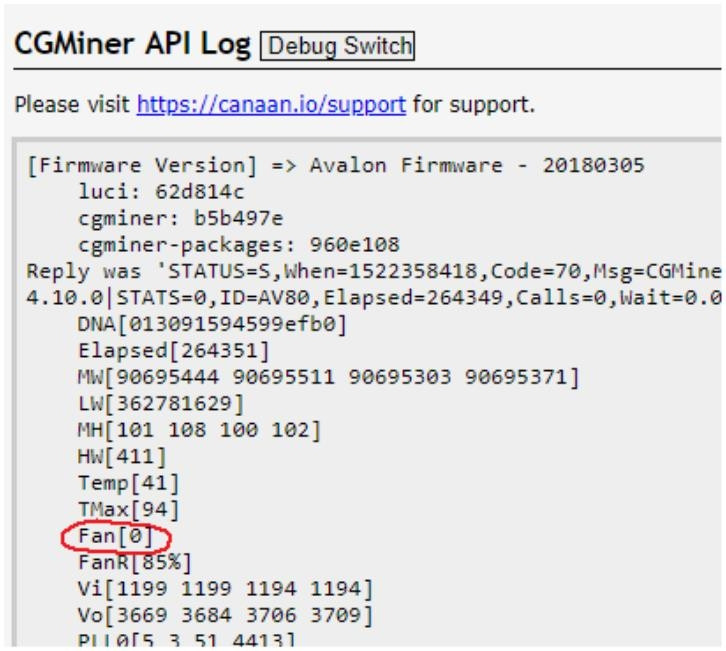
6. AvalonMiner Controller / Raspberry Pi troubleshooting
If you cannot access the controller unit at all and you have double-checked that your setup is ok, then it is possible that your controller unit is faulty and needs to be replaced with a new one.
Please also make sure that the 5 VDC wall wart is in ok condition and can provide at least 5 VDC 2.5 A power for the controller unit.
Here is the list of compatible controller units:
• AvalonMiner Controller (RPi 3 based device)
• Raspberry Pi 1 Model B
• Raspberry Pi 2 Model B
• Raspberry Pi 3 Model B
7. AUC3 Converter troubleshooting
Suppose you can access the controller unit successfully, but you don’t see any miner devices connected. In that case, there may be a faulty AUC3 converter or a faulty control board (MM board).
You can look at the LED colors and log error codes and figure out the issue that way.
You can try a spare AUC3 converter if you have another one.
You can quickly troubleshoot if it is the AUC3 that is faulty if you have ten miners or more in your setup.
This means that you have at least two AUC3 converters in your setup. You can swap those two AUC3 converters and see if the issue moves to another group of miners. If it does, you should be able to know which one is the faulty AUC3 converter.
8. Control board (MM board) troubleshooting
If you can access the controller unit successfully but don’t see a miner device connected, there may be a faulty AUC3 converter or a faulty control board (MM board).
Another example of possible control board malfunction is a vast number of hash boards down suddenly.
One good hint is that you have, for example, five miners connected to one AUC3 converter, and you are only able to connect four of them. It indicates that there might be issues with one miner control board.
You can look at the LED colors and log error codes and figure out the issue that way.
You can try using a spare control board (MM board) for the miner in question if you have another one.
9. PMU board troubleshooting
PMU board stands for Power Management Unit board.
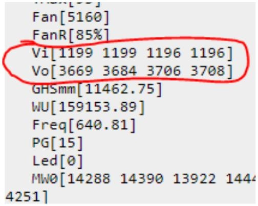
If you have one or more hash boards down and without power, it is a good idea to figure out the PMU board condition. You can do this by looking at the CGMiner API Log.
If you any values zero or values having an odd number, you may have a faulty PMU board. When you look at the log, please pay attention to Vi and Vo values (voltage in and voltage out).
One PMU board has two power terminals, so there are four values visible in the log. Four digits present the measured input voltage and output voltage. For example, value 1199 means 11.99 VDC.
Both PMU boards are working normally.
![]()
![]() The second PMU board is not working at all.
The second PMU board is not working at all.
![]()
![]()
![]()

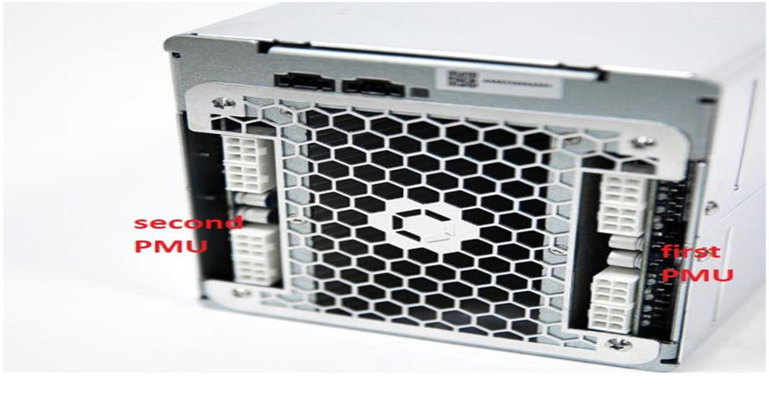
In this next image you can see how to identify which PMU board is the first one and which is the second.
To find out if you have a hash board issue, you can look at two things in the CGMiner API log.
• Works (MW0 – MW3)
• Chip temperatures (PVT_T0 – PVT_T3).
If there is one board showing no Works, then it is a faulty one.
Your miner might also have issues with constant rebooting because one of the ASIC chips overheats.
In this case, you can first clean the old Antminer thermosetting adhesive and then apply the new Antminer thermosetting adhesive.
If the new Antminer thermosetting adhesive does no good, you need a new hash board.
Number of works shown in the log. This miner is working normally.
 Every single ASIC chip temperature shown in the log.
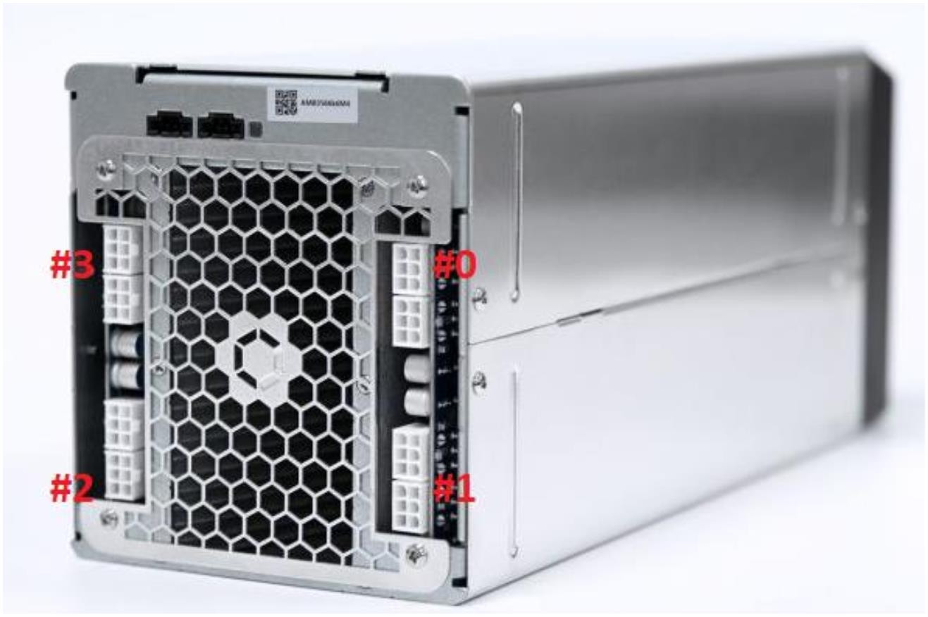
 In this next image you can see how to identify which ID number is for which hash board.
III. Tear down
You mostly need only one tool for the tear-down process, and it is a portable electric screwdriver. Ensure you have a good quality Phillips head screwdriver and right-sized to avoid damaging the small bolts.
Please also be careful not to use too much force, potentially damaging your screwdriver, bolt, or thread.
Please pay attention to using the correct type of bolt when assembling it all back together.
These instructions show you how to separate each miner component so that you can replace a faulty part in question with a new spare part.
Step 1: Steel tube case Remove the steel tube case.
There are four small bolts on both sides of the miner, so eight bolts.
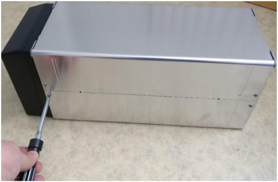
Removing the steel tube case.
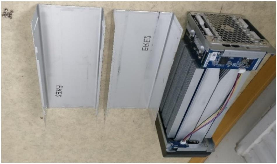
Steel tube case removal completed.
Step 2: Cooling fan
Remove the cooling fan. Four screws are holding the cooling fan shroud against the frame.
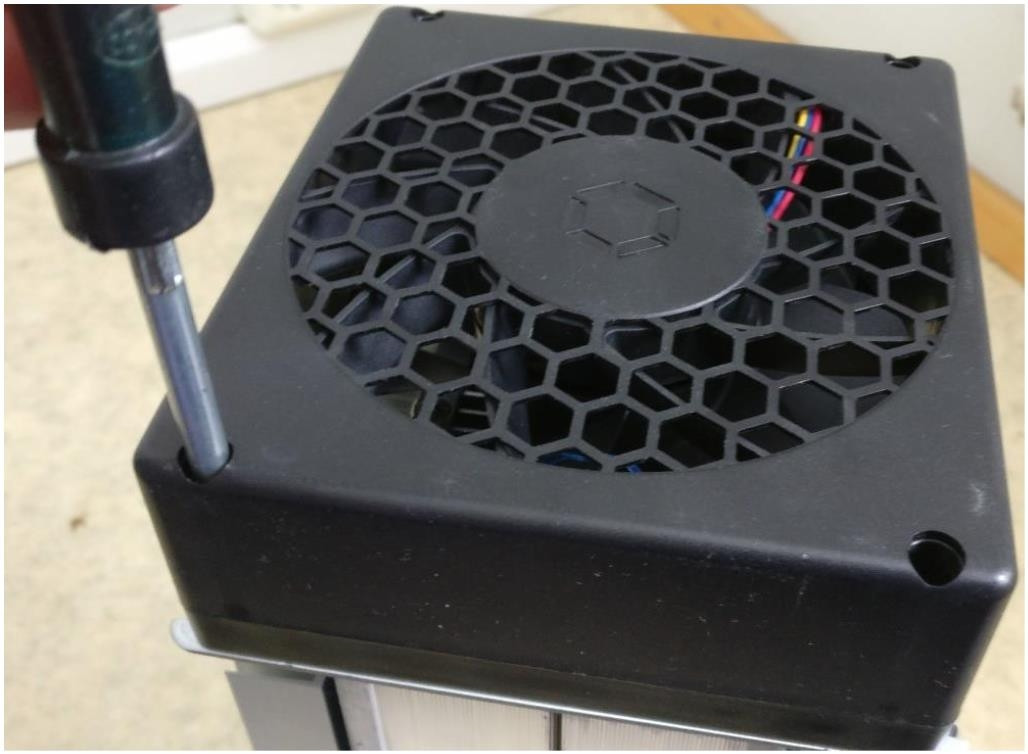
Removing the cooling fan shroud.
Unplug the 4-pin fan cable connector and remove the cooling fan.
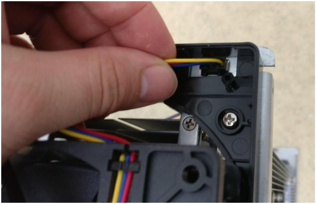
Removing the cooling fan.
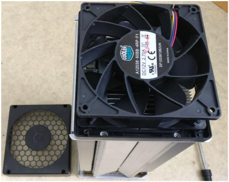
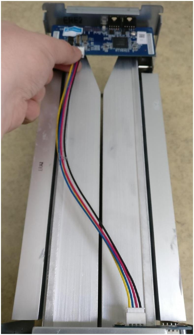
Step 3: Cooling fan extension cable
Unplug the 4-pin fan extension cable from the control board.
Step 4: Control board (MM board)
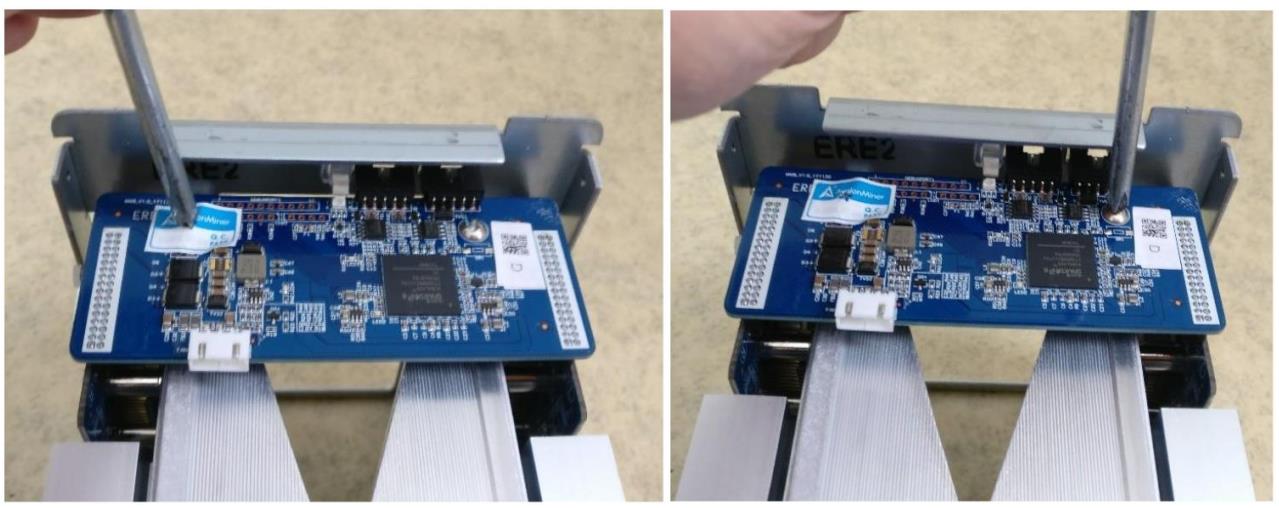
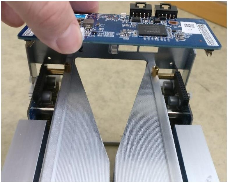
Remove the control board (Miner Management board).
There are two small bolts to be removed, after which you can gently detach the control board, which is connected to both two PMU boards (Power Management Unit).
Step 5: Steel grill
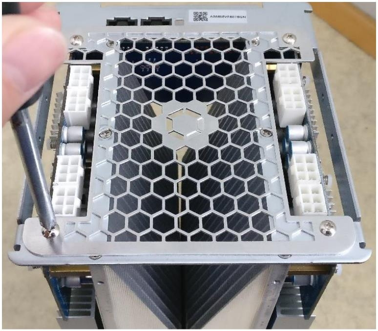
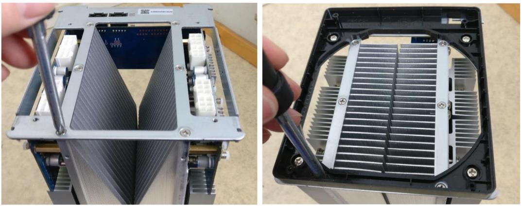
Remove the hexagon pattern steel grill.
Four small bolts are holding it against the frame.
Step 6: Frame parts
Remove both two frame parts.
Six small bolts hold one frame part against the heat sinks, so a total number of twelve bolts.
Step 7: PMU board
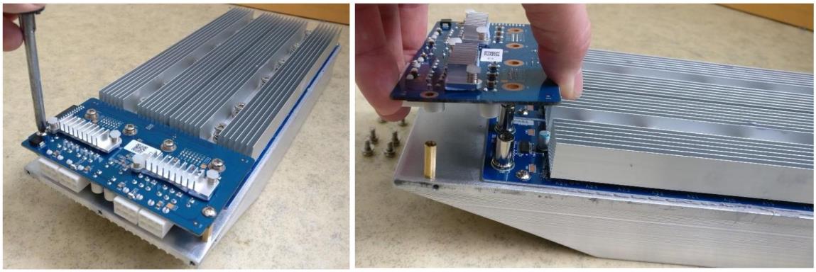
Remove both two power management unit boards (PMU board).
There are six bolts per PMU board and four of them connect the power from the PMU board to the hash board, so a total number of twelve bolts.
 Step 8: Hash board
Remove the hash board.
There are three small bolts and six big bolts holding one hash board against the heat sinks.
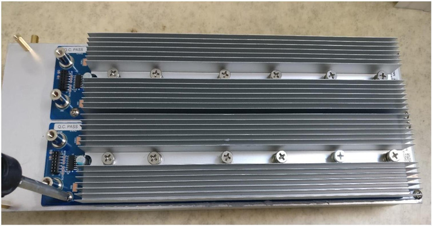
Two hash boards with one shared large heat sink and two individual heat sinks.
Please remove the old paste if needed, if it is hardened or damaged in any different way. You should do this by using pure isopropyl alcohol and a soft cloth or paper.
You can also use a cotton swab if needed.
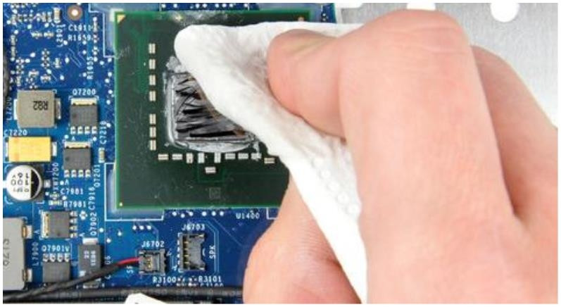
After the surfaces are cleaned, you can apply a new thermal paste. When applying the new thermal paste, do not use your finger or anything else that causes impurities to mix with the thermal paste.
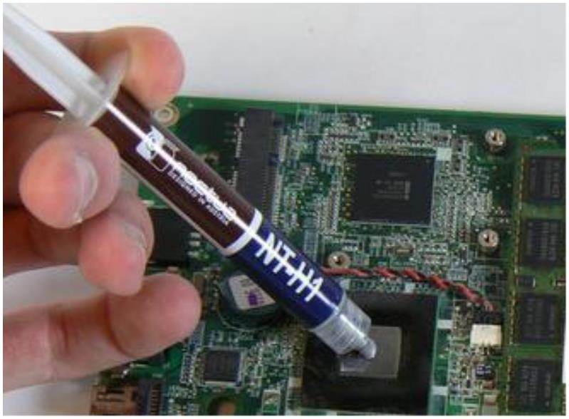
Assembling it all back together is essentially doing this same process backward.
IV. Conclusion
These instructions should be able to help you with most of the issues that might occur, even though AvalonMiner failure rate in field is close to 1%, which is a low number compared to the competitors.