


Avalon A10 Series Troubleshooting Guide
Overview
Thank you for choosing our products. To ensure that you can fully understand and install this product, please read the manual carefully. After reading, please keep it in a safe place for future reference.
Safety regulation
Warning: To prevent accidents that threaten human safety, such as equipment damage, fall, electric shock, fire, etc., please install and use it strictly by the instructions. You cannot modify the equipment and replace parts by yourself.
• Do not use a power supply that exceeds the rated voltage range.
• Do not place the device in a hazardous location.
• When inspecting and repairing equipment, please entrust professional operations.
• When the equipment is abnormal, please cut off the power quickly and contact the after-sales service.
Hardware Connection
Connect the power supply and product as shown below:
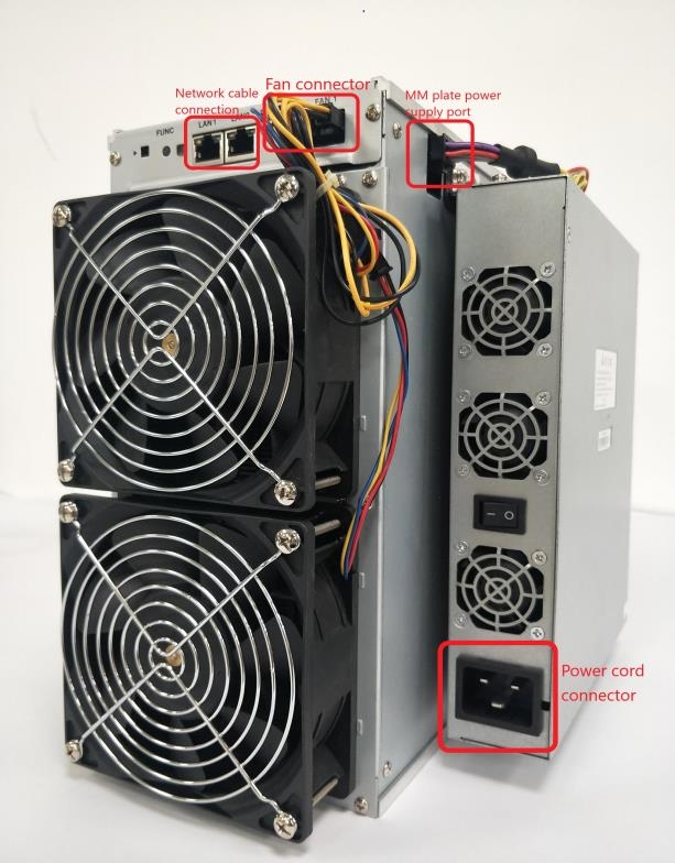
Power connection
Fix the adapter board to the miner with six M3 * 4 screws as shown in the figure. Push the power supply into the card slot as shown in the figure.
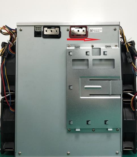
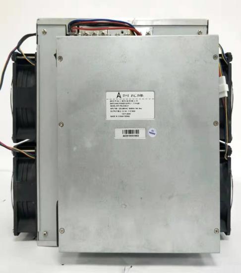
Use twelve M4 * 8 screws to connect the output conductive copper bar as shown in the figure below to connect the power supply to the miner.
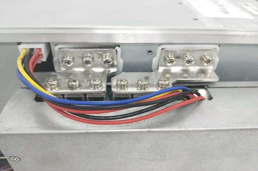
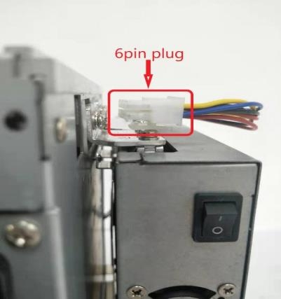
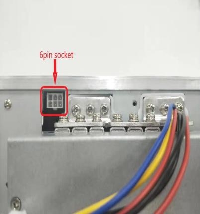
Insert the power 6pin plug into the 6pin socket of the miner as shown below.
Serial Connection
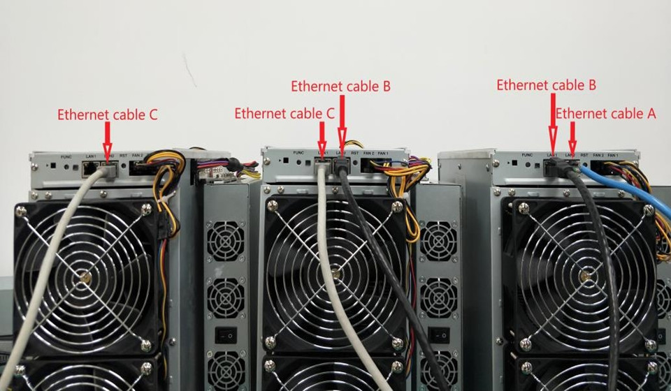
Each miner is equipped with two network ports, which can be connected by A network cable (up to 12).
An example is as follows. Network cable A is connected to a switch (or router). The first miner and the second miner are connected in series with a network cable B. Finally, the second miner and the third miner are connected in series with a network cable C.
Button and Indication LED
 Button
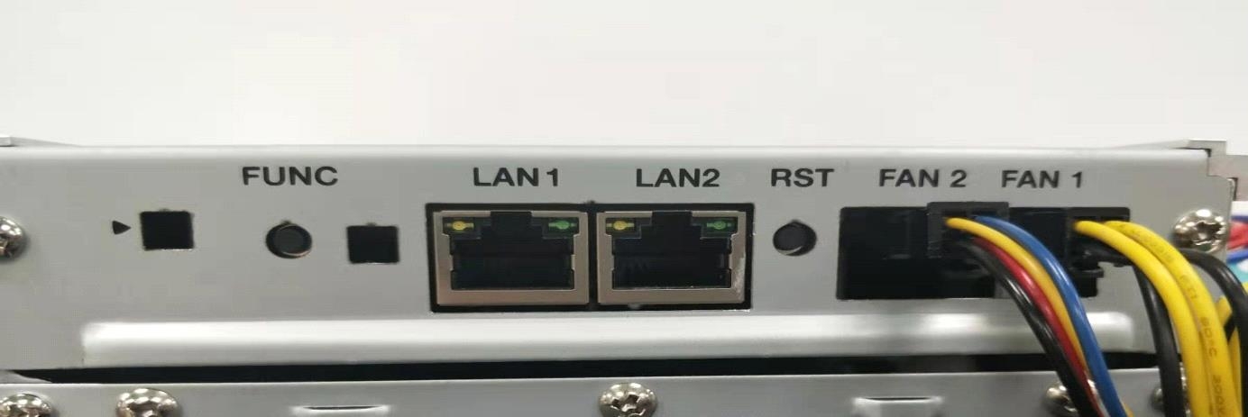
RESET: System reset button. System reset will not affect internet concatenation.
FUNC: Function keys, which can be used to restore the factory configuration, enter configuration mode, switch lighting status during operation, etc.
Indication LED
• The indicator light flashes red several times after power-on.
• After the device starts, the indicator lights up in white for about three seconds. During this period, pressing the FUNC key will enter the configuration mode.
• Normal mining condition, indication LED is Green.
• System initialization period, LED is yellow.
• System overheat condition, LED is RED.
• During system operation, through FMS software or manually pressing the FUNC key, the indicator light is always white, press it again to restore the original color.
• Restore factory settings: When powering on (before the indicator flashes red), press the FUNC function key for five seconds until the white light flashes to indicate success, then press RESET or disconnect the power to restart.
Work mode
This device has two working modes: "normal mode" and "configuration mode."
Normal mode
Normal working mode. The device runs in this mode for most of the life cycle of the device. In this mode, the network can use DHCP (dynamic acquisition) or static IP.
Configuration mode
During the white light after startup (about three seconds), press the FUNC key, the device will enter this mode.
In this mode, the IP address is static (address: 192.168.168.168, subnet mask:
255.255.255.0). You can access the built-in Web service of the device through a PC browser and then configure the network, mining pool, password, and other information.
Set the PC to a static IP address: 192.168.168.100 (or any other non-conflicting address on the same network segment), subnet mask: 255.255.255.0, and connect to the same network with the device (under the same switch or router, or the PC and Device network cable is directly connected.)
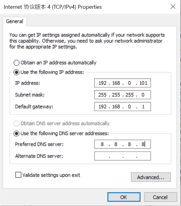
1. Click , Open the Network and Internet settings.
2. Change adapter options, disable WLAN, enable Ethernet.
You can use a browser to access http://192.168.168.168/ to configure the device (modify a static IP, etc.) After the configuration of the device is completed, it needs to be restarted to take effect. You can click Reboot on the left side of the console or restart it manually. Don’t forget to switch the network connection so that your device cannot access the internet.
Revisit the modified IP address using a browser. If the indicator is green, the operation is correct.
System setting
Access the device's built-in web service through a browser, and log in to the device console.
User Log
Default user: root. Default password: root. After logging in, you will see the Overview page.
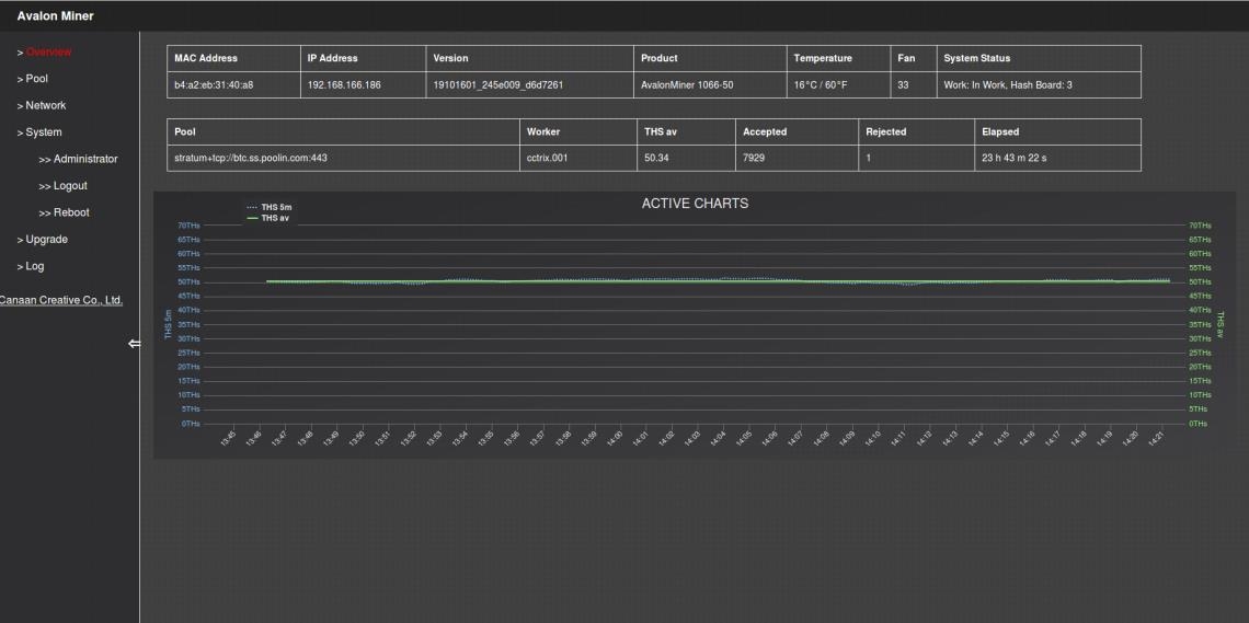 Network setting
Click Network on the left side of the console, it can be set to DHCP (Dynamic Acquisition) or Static IP (Static).
Note: After saving the network settings, you must restart to take effect. You can click Reboot on the left side of the console or press the RESET button to restart, or you can disconnect the power and restart the power.
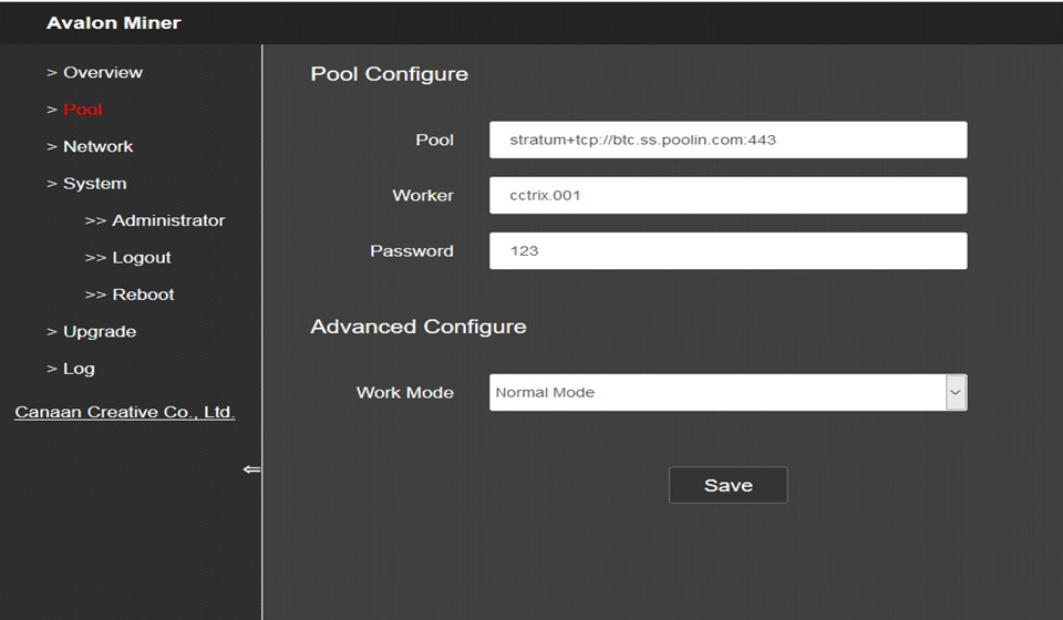
Pool Setting
The figure below is the factory default setting. Work Mode can be selected from Normal Mode (low power consumption mode) or High Performance (high power consumption mode). When using High-Performance mode, please pay attention to using a higher power output power supply Socket to prevent damage to the hardware.
Note: After the mining pool configuration is saved, it must be restarted to take effect. You can click Reboot on the left side of the console or press the RESET button to restart, or you can disconnect the power and restart the power.
User Password
Default Username: root. Default Password: root.
Click Administrator on the left side of the console to set a new password and save.
Firmware Upgrade
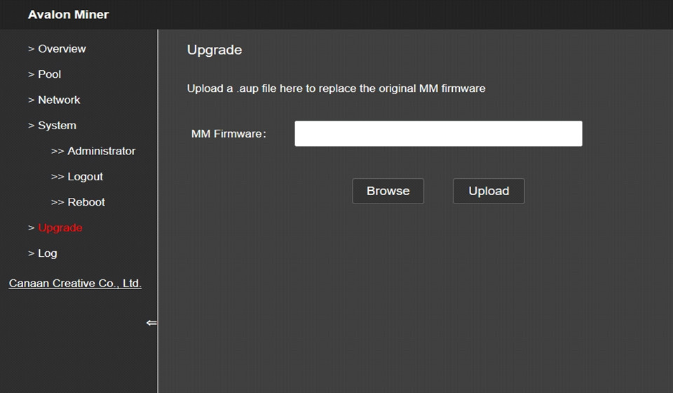
The file format of the upgrade package for this device is * .aup, which can be downloaded from the official website or contact customer service. The firmware upgrade of this device can be performed by FMS software.
The firmware upgrade of this device can be performed by FMS software.
Reset to Default setting
When powering on (before the indicator flashes red), press and hold (Five to ten seconds) the FUNC key. The system will automatically clear the saved configuration, including network, mining pool, password and other information. The indicator frequently blinks white after the configuration is cleared, indicating that the configuration restoration was successful. After releasing the FUNC key, press the RESET button to restart or disconnect the power supply and power on again. The system will work with the default factory configuration.
Malfunction self-examination
Boot Failure
1. Failure Phenomenon
Miner fan does not turn on or LED light does not turn on after boot.
2. Possible Cause
The fan wiring of the miner is loosened, the power supply line of the control board of the miner is disconnected, the AC power input is not connected, the power module is broken, the control board is broken, and the power output is short-circuit protected.
3. Inspection and repair method
• Power on the whole miner, turn on the power switch of the miner, and plug in the network cable connected to the switch (or router). Check that the network port link light is blinking. If the network portlight is off, the MM control board is out of power.
You need to check the power cable connection, replace the power supply, or check whether there is a short circuit in the power output.
• If the network port light is on, but the MM control board LED is off, you need to replace the MM control board.
• If the MM control board LED is on but the fan does not rotate, check the fan cable or replace the fan.
Can’t Mining
1. Failure Phenomenon
• The mining pool cannot be connected for a long time (more than 5 minutes) after booting up (the miner lights up a yellow for a long time, does not turn green, and has no hash rate).
• The miner can be connected to the mining pool after power on (miner's LED light is green), but no hash rate.
2. Possible Cause
• POOL configuration fault.
• Network configuration fault.
• Miner can’t go outside the network.
• Miner power doesn’t have main output(fault wire connection, overload, short or broken).
• Miner hash board can’t work.
• Miner overhot Protection.
3. Check and repair
• If you cannot use the PC to connect to the miner through the network, you can try to restore the factory settings after confirming that the network environment is normal, the network cable is firmly connected, and the miner is turned on normally. For the method of restoring factory settings, see Appendix 1.
• Check the current firmware version of the miner. It is recommended to use FMS to update to the latest version. For the upgrade method, see Appendix III.
• Check hash board status.
• Click Overview to check the operational status shown in ② in the figure below. Usually, it should be In Work. If OverHot indicates overheating shutdown, you need to check the fan and ambient temperature as follows.
• Check the number of Hash Boards shown in ③ in the figure below. For 104x series, the value should be 2. If the value is 1, you need to contact our after-sales personnel to deal with it. If it is 0, you need to check the power status according to the following.
 1) Check Power, temperature, network status, fan status.
Click Log on the left side .see below:
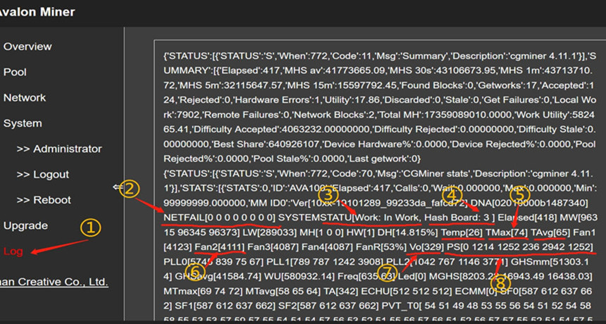
Check the following fields in the suitable interface:
• NETFAIL(As shown in②):Recorded the time of disconnection from the mining pool (if it has not been disconnected or has never been connected to the mining pool, it is all 0 here). In this record, the odd-numbered items (items 1, 3, and 5) are when the mining pool was disconnected, and the even-numbered items (items 2, 4, and 6) are when the connection to the mining pool is restored. For example, suppose only the odd-numbered items have data and the even-numbered items are 0. In that case, it indicates that the connection to the mining pool is currently disconnected and has not been restored (usually because the server at the mining pool end is overstressed and disconnected. If it frequently occurs for a long time, you can replace other mining pools with mining.) SYSTEM STATU: Records the current working status, normally In Work (as shown in ③.) Among them, Hash Board (shown as ④): the number of hash boards in operation, for 104x models, it should be 2. If it is 1, you need to contact the after-sales service. If it is 0, you need to check the status of the power supply further.
• Temp is ambient temperature, not exceeding 35℃。
• TMax is highest ASIC IC temperature, not exceeding 85℃。
• TAvg is average ASIC temperature.
• If you see any of the above temperature items are too high (Temp exceeds 35, Tmax exceeds 85, TAvg exceeds 68), you need to check the fan speed (as shown in ⑥).
For 104x models, only Fan1 and Fan2. If the fan speed is average, you need to reduce the indoor temperature and ensure good ventilation around the miner.
• Vo (shown as ⑦) is the average chip voltage, which is normally 32x.
• PS (shown as ⑧) is the power state. The meaning of items 1-6 is as follows:
a. Item 1: Error code. Normal is 0. Other values indicate power failure or output short circuit.
b. Item 2: Voltage supplied to the control board. Normal is 12xx.
c. Item 3: Voltage (unit: 10mV) for the hash board (normally between 1200 and 1400).
d. Item 4: The current output by the power supply to the hash board, specifically related to the output power and voltage.
e. Item 5: The output power from the power supply to the hash board. For 104x models, the normal value is between 1800-2500 (in W).
f. Item 6: The expected output voltage from the power supply to the hash board, configured by the control board.
If the six parameters of the power supply PS field are all 0, the control board cannot communicate with the power supply. Please check the line connection. If the connection is correct, the power supply needs to be replaced.
2) Check whether the configuration of the mining pool, miner, and miner passwords is correct.
In the backstage of the miner, click Pool on the left side, check the configuration of Pool, Worker, Password, and finally click the Save button to save the settings.
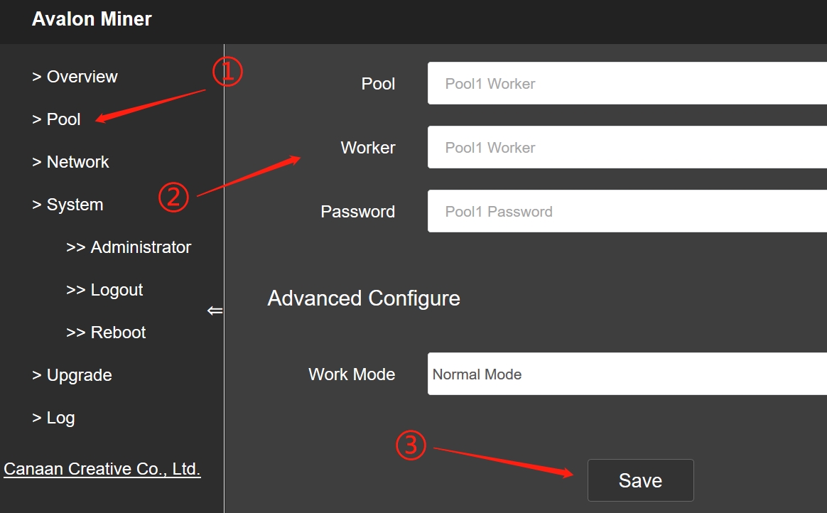 3) Check Network setting
a. Click NetWork on the left. The default configuration is DHCP mode. If all data here is empty, press F5 to refresh the page.
b. If you use a static I P, pay attention to the DNS configuration. Incorrect DNS configuration will cause the miner to be unable to access the mining pool.
c. The DNS address commonly used in China is 114.114.114.114, and the DNS address commonly used outside China is 8.8.8.8.
Notice: After modifying the configuration, you need to click the save button to save the configuration.
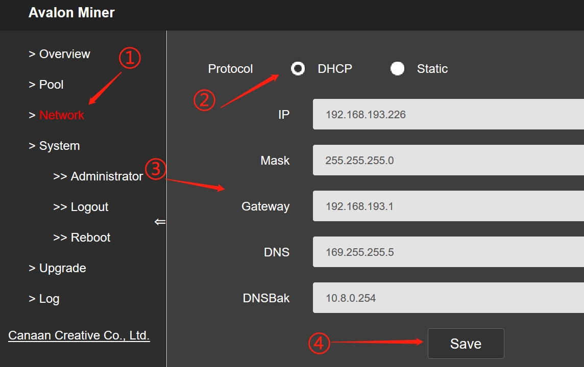 Appendix Restore the default setting SOP
• Restore default setting method 1
Step | Remark |
Makesure the miner is power off. | |
Press the func button and keep it pressed. | |
Power on the miner. | Note that you need to keep the func key pressed. |
Keep the func pressed until the white LED of the miner flashes. |
• Restore default setting 2
Step | Remark |
Miner can’t connect to power. | |
Press func button and keep pressing status. | |
Press reset and release. | Note that you need to keep the FUNC key pressed. |
Keep the func pressed until the white LED of the miner flashes. |
Appendix 2 Firmware version Check
2 methods to check the firmware version:
View version in the backstage:
Click on the left column Overview, you can see the firmware version number marked by ② in the figure below.
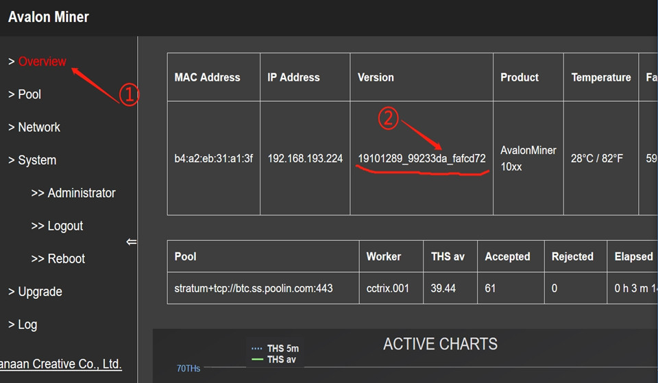
Use FMS to check:
Directly check the rightmost column of the miner list in FMS, as shown in the following figure ①.
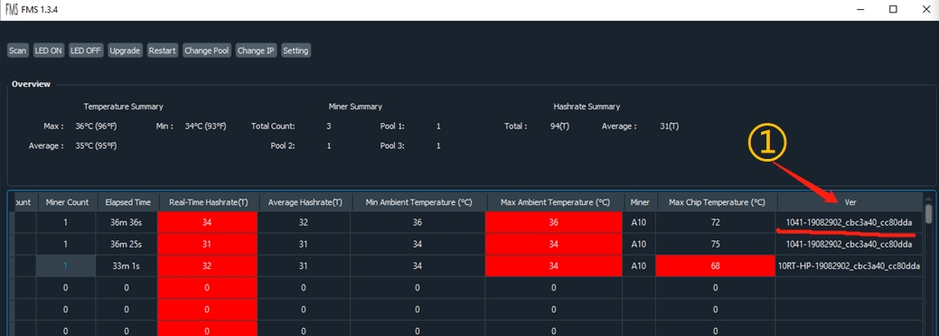
Appendix 3 FMS Operation method for a batch upgrade of miner firmware
Start FMS, select the corresponding miner in the main interface, and click the Upgrade button, as shown below:
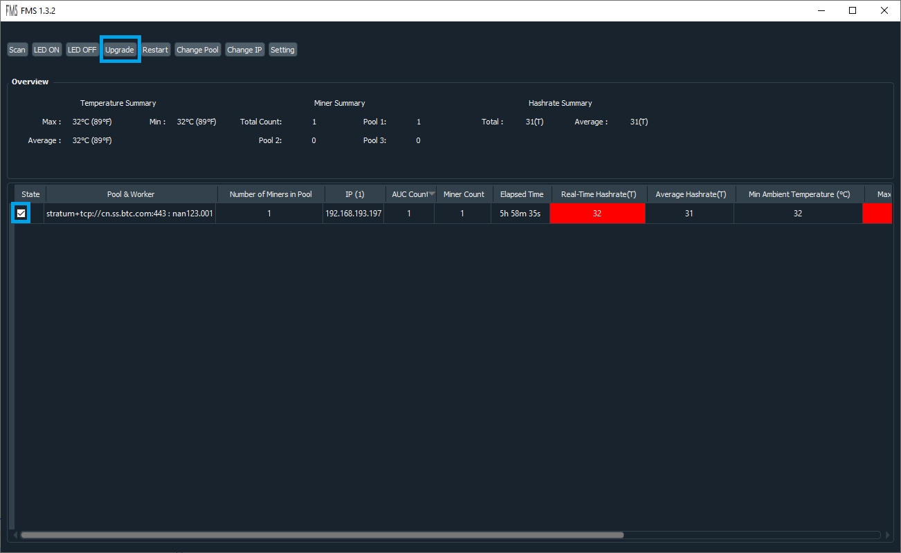 In the dialog box that appears, select the firmware file to be upgraded and click open. As shown below:
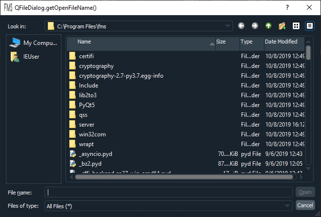
There will be progress prompts during the update process:
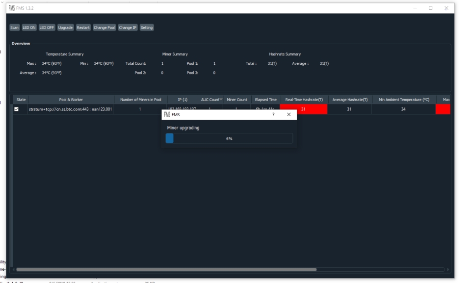
At the end of the update, there will be a prompt. If all are successful, all upgrades were successful. Otherwise, all IP addresses that failed to be upgraded will be listed.
For the miners that failed to upgrade, you can select them according to
the IP and click RESTART to restart them. Then, wait 3 minutes and try to upgrade these miners again.
APPENDIX 4 Log Page main parameter
Field | Name | Remark |
Elapsed | Total running time after the miner starts (unit: second.) | |
Ver | Miner firmware version. | |
DNA | The world's only miner ID. | |
NETFAIL | After the mining pool is successfully connected, the time to disconnect from the mining pool and the time to resume the connection. | The odd numbered items (items 1, 3, and 5) are the time to disconnect from the mining pool, and the even numbered items (items 2, 4, and 6) are the times to restore the connection to the mining pool. The time is in seconds, and the startup time of the miner is the 0th second. |
SYSTEMSTATU | Current system status, including working status and number of hash boards in operation. | |
DH | The average calculation error rate. Normal value 0.6-1.6%. | |
Temp | Ambient temperature. | |
TMax | Maximum chip temperature | |
TAvg | Average chip temperature | |
Fan1 | Fan 1 rotate speed | |
Fan2 | Fan 2 rotate speed | |
FanR | Fan rotate Percentage | |
Vo | Average chip voltage | |
PS | Power state | The meaning of items 1-6 is as follows: Item 1: Error code. Normal is 0. Other values indicate power failure or output short circuit. Item 2: Voltage supplied to the control board. Normal is 12xx. Item 3: The voltage supplied to the hash board (HASH board) is normally between 1200 and 1400 (unit 10mV). Item 4: The current output by the power supply to the hash board, which is specifically related to the output power and voltage. Item 5: The output power from the power supply to the hash board. For 104x models, the normal value is between 1800-2500 (in W). Item 6: The control board configures this voltage. If the six parameters of the power PS field are all 0, the control board cannot communicate with the power. |
GHSmm | Theoretical hash rate in GH/ s. | Note: The actual hash rate is the value obtained by subtracting DH (calculation error rate) from the theoretical hash rate. |
GHSavg | 1 hour average hash rate | The 1-hour average hash rate calculated based on the submitted work is the closest to the 24-hour average hash rate at the mining pool end. |
Freq | Equivalent frequency | The chip works at different frequency points, and the equivalent frequency is the comprehensive equivalent frequency of the whole machine. |
Led | White LED light status | When you need to find a specific one among many miners, use the API to light up the white LED of the miner. Here is whether the white LED light is on, 1 means it is on, 0 means it is off. |
MGHS | hash rate of a single hash board in GH/s | |
MTmax | Maximum chip temperature in a single hash board. | |
MTavg | The average chip temperature of a single hash board. | |
TA | Total number of ASIC chips | |
SF0 | Frequency distribution status of hash board 0. | For example, SF0 [500 525 550 575] means thatfrequency point 1 is 500MHz and frequency point 4 is 575MHz. |
SF1 | Frequency distribution state of the hash board 1. | |
PVT_T0 | List of the temperature of all chips on hash board 0. | |
PVT_T1 | List of the temperature of all chips on hash board 1. | |
PVT_V0 | List of the voltage of all chips on hash board 0. | |
PVT_V1 | List of the voltage of all chips on hash board 1. |
APPENDIX 5 LED status
1. LED lamp status flow process under normal startup:
Status | Red LED Blink | White LED on | Yellow LED On | Green LED On |
Duration | 1s | 1s | Approximately 20-30s | Long time |
2. LED status condition
LED Status | Description |
Off state | The firmware is not running. (Possibly no power input). |
Flashing red | Blinks for 1s before system startup. |
White LED on | Lights up for 1s before system startup, or uses API control to light up. |
White LED Blink | The system enters test mode. (Or restore the state after the factory setting operation, you need to release the func button and restart to make the master control enter the normal working state.) |
Yellow Light on | The system is started but not connected to the mining pool. Or prompt when switching to the frequency reduction mode. |
Green LED on | The system has been started and connected to the mining pool. |
Dear Customers,
Hello, April 4, 5 and 6, 2025 (GMT+8) are the traditional Chinese festivals - Qingming Festival. Our company will suspend shipments during these 3 days and resume shipments on April 7 (GMT+8). We are deeply sorry for the inconvenience. Thank you for your understanding and support.
Best wishes,
ZEUS MINING CO., LTD