

Innosilicon T2 Series Repair Guide
1. The temperature of the maintenance air gun and the waveform diagram of the oscilloscope
1) Maintenance air gun: portable desoldering gun
Because the T2 hash board heats up quickly, the desoldering gun is an auxiliary tool, and the muzzle of the desoldering gun is heated directly above the hash board during use.

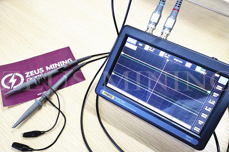
2) Oscilloscope features
Full touch screen 7-inch large screen; dual-channel input; intelligent anti-burn; has three trigger modes of automatic, single-shot, and normal; one-key automatic adjustment; manual cursor measurement; one-key save, one-key screenshot waveform; powerful Waveform picture processor; USB picture display, etc.

3) Function buttons for commonly used gear positions of the multimeter Fluke 15b+

4) The amount of Antminer thermosetting adhesive and how to use it:
Pick an appropriate amount of thermosetting adhesive on the bottom of the heat sink, then stick it to the IC of the hash board and straighten it, turn on the desoldering gun to adjust the temperature to 250 degrees-300 degrees, blow it against the heat sink for 5 minutes-10 minutes, and then the fan will cool.


2. Explanation and elimination of common failures of the whole miner
1) Hash board heat sink is incomplete
Use the test tool putty to test the abnormal hash board.
a. If the test result shows ng, it means that the hash board is faulty, and the hash board needs to be repaired;
b. If the test result shows pass, it means that the hash board is OK, and the faulty parts can be located one by one for the power supply/control board/data cable. If the power/data cable is replaced and the fault still exists, the control board needs to be repaired.
2) The miner repeatedly restarts
a. First restore the control board to factory settings or erase and re-burn;
b. If re-burn is invalid, you can use the test tool putty to test, locate the faulty hash board and repair it;
c. Test the three hash boards all show pass. You can try to replace the power supply and then restart.
3) The network is abnormal
Observe whether the network portlight is always on
a. If the network portlight does not light up, check whether the network port is blocked by foreign matter or dirt. If the fault still exists after clearing, you need to repair the control panel;
b. If the light is on, you can try to press and hold the IP set button for 8 seconds to restore the factory settings and search for the IP again to connect.
4) The whole machine is not powered on
a. Replace the power supply;
b. Replace the control board;
c. The hash board is short-circuited, and the three hash boards can be pulled out for power supply to check one by one.
5) The temperature of the miner case is too high
Check whether the front and rear fans usually rotate or whether there are foreign objects blocked.
3. Explanation and troubleshooting of common faults of the hash board

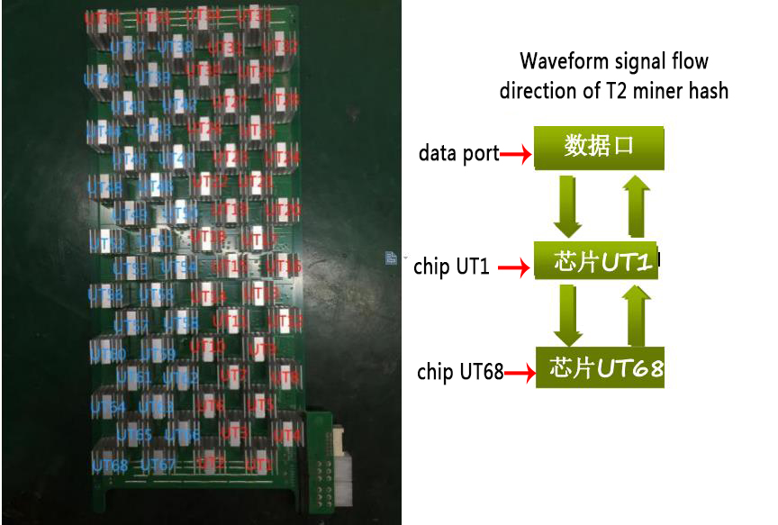
Waveform test point and reference voltage test point A

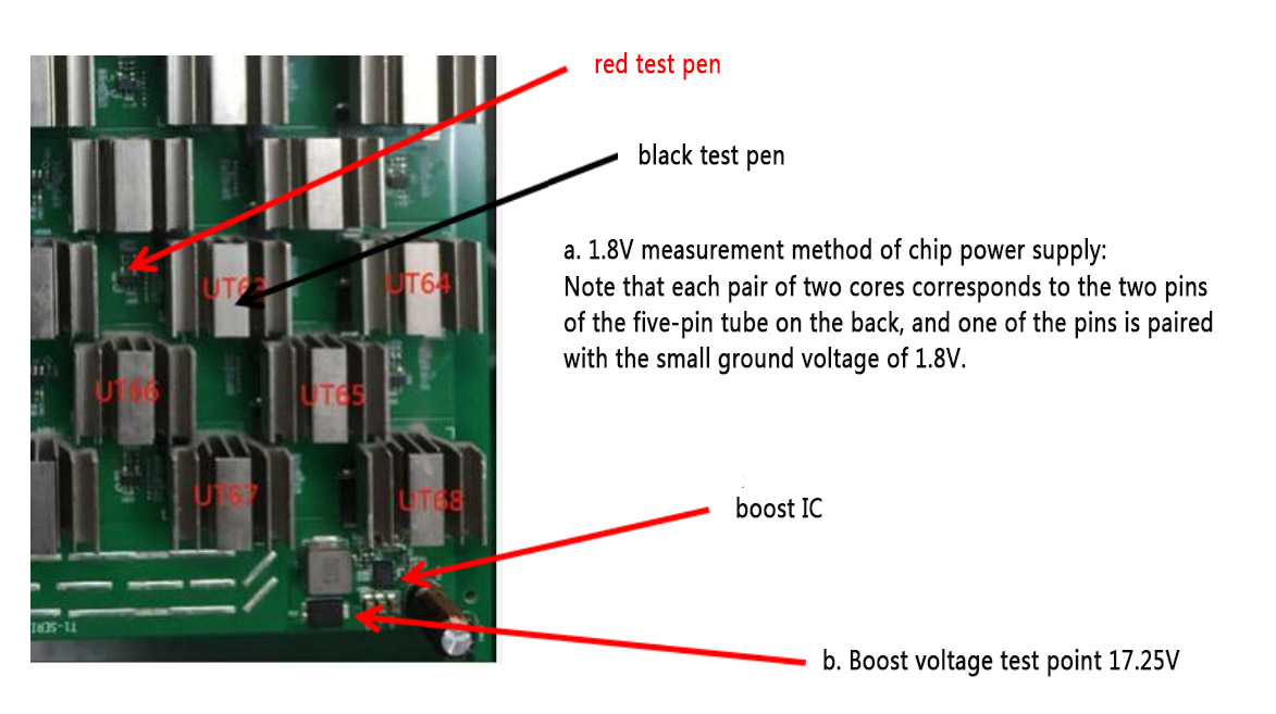
Waveform test point and reference voltage test point B


Type of errors
Mark | Describe | Remark |
E0 | CHIP_TYPE not found | No link |
E1 | Single-chip core number<chip core*30% | Statistics under working frequency |
E2 | The total number of cores on the board<total core*90% | Statistics under working frequency |
E3 | single chip softbist error rate ≥ 99% | |
E4 | The chip on the board has pll and does not lock | |
E5 | chip temperature exceeds [-40, 125] | The software reports 9999 or -9999 |
E6 | 1 The voltage of the chip is less than 0.38V at the default frequency and pll is not locked 2 The voltage of the chip is greater than 0.6V at the default frequency 3 The voltage of the chip is greater than 0.6V or the voltage is less than 0.38V at the operating frequency | |
E7 | command returns failed | “E7 : :0”means pll configuration failed |
E8 | chip softbist total error rate> 50% |
If there is no problem in the detection, print '√, 'otherwise print '×.' When a problem is detected, the software will report the error type with the highest priority. The order of error priority is: E0> E6> E4> E7> E5> E3> E1> E2> E8. The report can guide the maintenance and replacement of chips.
1) E0: XX, replace the XX chip
E0:1 fault exception
The first step is to check whether the output of UT1 has a CLK clock signal
a. If not, use an oscilloscope to measure R61; if there is, UT1 may be wrong or false welding;
If not, measure whether the U38 output pin has a clock power supply of 1.8V; if so, replace the clock Y1;
b. If UT1 has a clock signal output, measure the voltage domain of each group of two chips at the beginning of UT1. The average value is about 0.45V. If the voltage value is 0.25V, note the position of the group that is lower than 0.18V. After changing one of them at will, the voltage can be increased. If there is no increase, then you can replace the other one in this group.
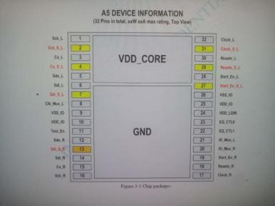
c. If UT1 has a clock signal output, and there is no one set of voltage domains lower than 0.18V, pay attention to whether the voltage domain of the abnormal group is around 0.27V. If the next group of voltage domains is normal to the following groups, It can be determined that there must be a five-pin tube burned out near the front and back of the set of sudden voltage changes. The output voltage of the five-pin tube is about 0.6V. Usually, it is 1.8V. Then a replacement is OK.
2) E1: XX
The XX chip is less core, replace the chip. (Such failures are less)
3) E2
The total core on the board is small. Check whether the total voltage of the circuit board is abnormal (refer to the method in E0 error). If there is no abnormality, the Hash board needs to be repaired or replaced with a new one. (Such failures are less)
4) E3: XX
The XX chip softbist has a high error rate. Replace this chip.
5) E4: XX
The XX chip pll is not locked, replace the XX chip or the XX-1 chip.
6) E5: XX
The temperature of the XX chip exceeds the standard, replace the chip. (Such failures are less)
7) E6: XX
The voltage of the XX chip is abnormal. After measuring the voltage of the same-level chip where the chip is located, confirm to replace the chip or the same-level chip (the measurement method is the same as E0, and the first chip in the voltage domain where the chip is located is replaced first. If the test still reports the same error, Then replace the second chip, and if an error is reported, replace the third chip; measure the SCK signal of the three-chip test points of this level, and replace the chip that frequently jitters).
If the fault is reported: E6:16 17 18, replace the UT17 chip.
8) E7: XX means that the pll configuration is not up, replace the chip. When the pll configuration fails, the starting voltage can be appropriately increased to test whether the circuit board can be configured with pll usually.
(First, replace the XX chip. If the test still reports the same error, replace the XX-1 chip. If an error is reported, replace the XX-2 chip, and if all errors are reported, replace the XX-3 chip.)

Main points of hash board repair
There are several necessary measurement reference voltages for the hash board, as follows:
First: LDO five-pin tube output voltage 1.8V (the failure point of each voltage may be caused by the burning of the two chips of the voltage supply or the short circuit of the capacitor next to the chip. The five-pin tube itself is burned out, and it can be replaced.)
Second: The voltage domain of each group of two chips is about 0.45V (the failure point of each voltage is that one of the two chips in the group is defective and the voltage is low. Replace one of them until the voltage rises)
Third: The voltage at one end of the D12 boost diode is about 17.25V, and it is about 16V before it is boosted (if there is no boost U39 D12 L3 C873 R797, any component damage may not boost 17.25V)
Note: There is a possibility that the test point will be connected to the point or the chip pin will be disconnected, or even the test point will be directly short-circuited to the ground. Check each possibility carefully with the waveform signal. The CLK and CS signals are the necessary condition signals for the chip. The CS signal is at the lower level of the wave device, so this signal is often ignored, and the failure point becomes its key factor.
4. Explanation and troubleshooting of common faults of control board

Main points of control board repair
1) Not start
A. First, try to erase and reprogram the control board and eliminate the possibility of software failure.
B. Check the TP1-6 test points of each power supply output of the control board hardware, whether normal or grounded.
a. If it is abnormal, the corresponding power supply regulator tube U10, U16, U17, U18, U19, U102 may be caused by lousy reset IC U6.
b. If TP1 3.3V is grounded, it is related to CPU U10 U102, FLASH flash memory, and network IC chip and can only be removed one by one and troubleshooting.
c. If TP3 1.8V is grounded, it is related to the CPU and network IC chip, and it can only be removed one by one and excluded.
d. The power supply is standard. Check whether the clocks Y2 and Y3 on both sides of the CPU have signals. If there are signals, the failure of the CPU, FLASH flash memory, and DDR will cause this fault. Replace them one by one to eliminate.
2) The network is abnormal
A. If the network is abnormal, first check if the network port light is on
a. If the light is not on, check whether the network cable port is dirty and try cleaning; if the cleaning is invalid, the measured X1 clock signal is standard, and the voltage at both ends of R47 is standard, and you can try to replace the network card IC chip.
b. If the light is on, measure whether the L10 inductor has a 1V voltage. If not, you can try to replace the network transformer or the network card IC chip.
3) CON data port is abnormal
A. Check whether the CON data port is dirty or blocked by foreign objects.
a. If there is no measurable comparison between the ground resistance of the problem port and the ground resistance of the standard port, if the standard data port has resistance on the same pin of the port, and the abnormal data port has no resistance, you can try to solder the CPU (U5) ;
b. If the resistance to ground is standard, you can take the hash board corresponding to another normal channel to cross-validate. If OK, it means that there is a problem with the channel's hash board, which has nothing to do with the control board; if the fault persists, you can try to replace the CPU (U5).
The content of this article is from the Internet, compiled and edited by ZEUS MINING.
Dear Customers,
Hello, April 4, 5 and 6, 2025 (GMT+8) are the traditional Chinese festivals - Qingming Festival. Our company will suspend shipments during these 3 days and resume shipments on April 7 (GMT+8). We are deeply sorry for the inconvenience. Thank you for your understanding and support.
Best wishes,
ZEUS MINING CO., LTD