


Note: CB4 V10 is an H6OS control board suitable for the WhatsMiner M20 M21 M30 M31 M32.
Step 1:Appearance Inspection
1. Check whether the component is falling from the control board's front and back. In case of physical damage, such as connector, inductance, and capacitance, replace the corresponding devices first.
2. Check whether there has a burnt-out chip issue. If it is burnt out, replace the corresponding chip first.
3. Check whether there is dust on the top and back sides of the control board. If there is dust, clean it with a circuit board cleaning solution or alcohol first.
Normal control board appearance as below:
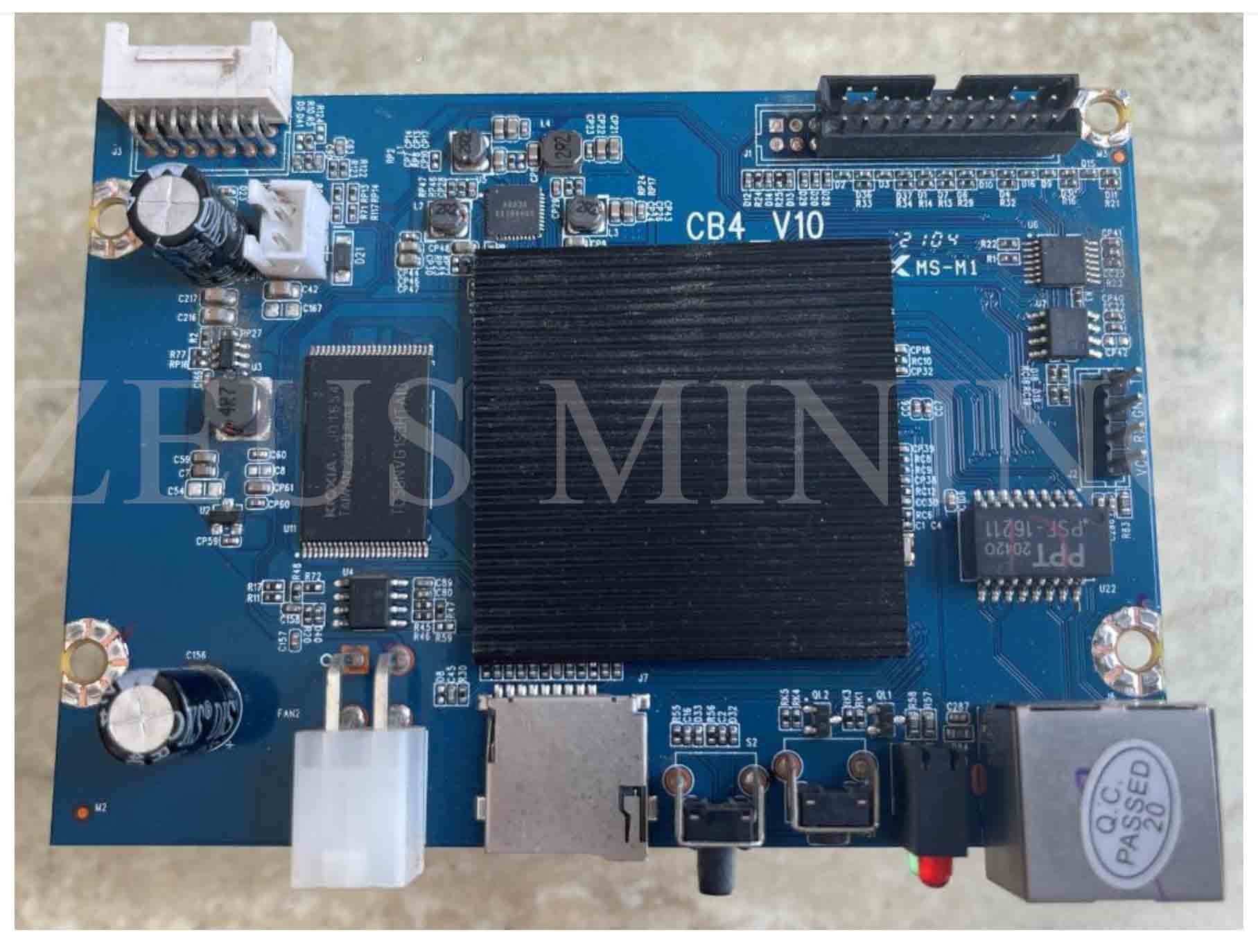
Pic 1 Top side of control board
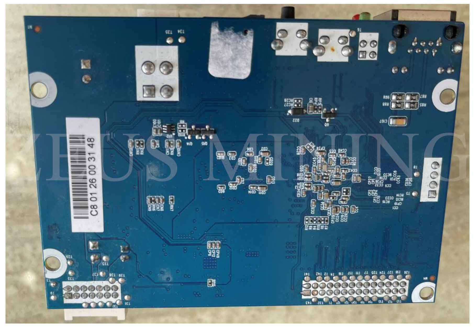
Pic 2 Back side of control board
Common component burnt issue as below: Top A-U3, Top B-U2, Back C:
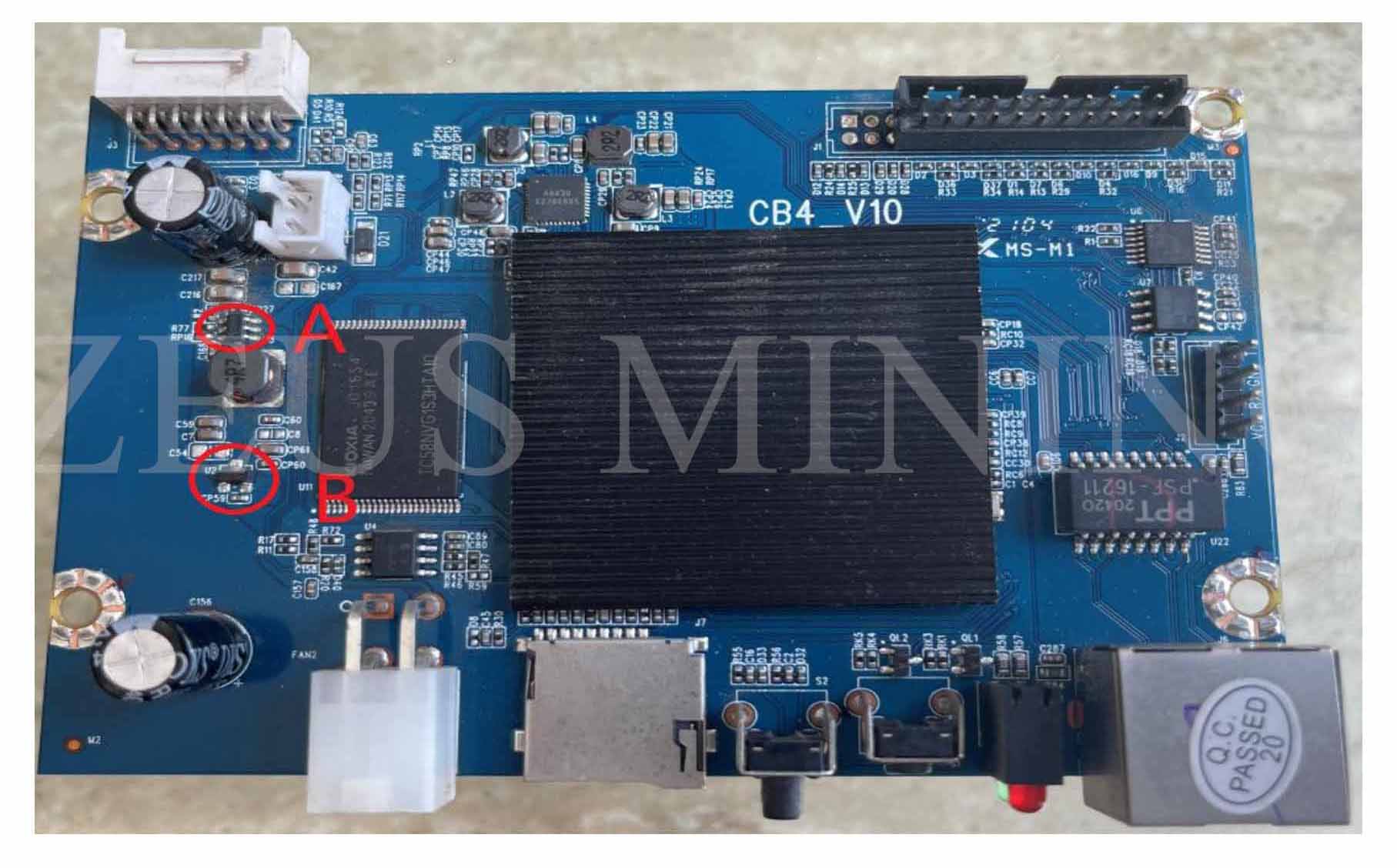
Pic 3 Top side A、B
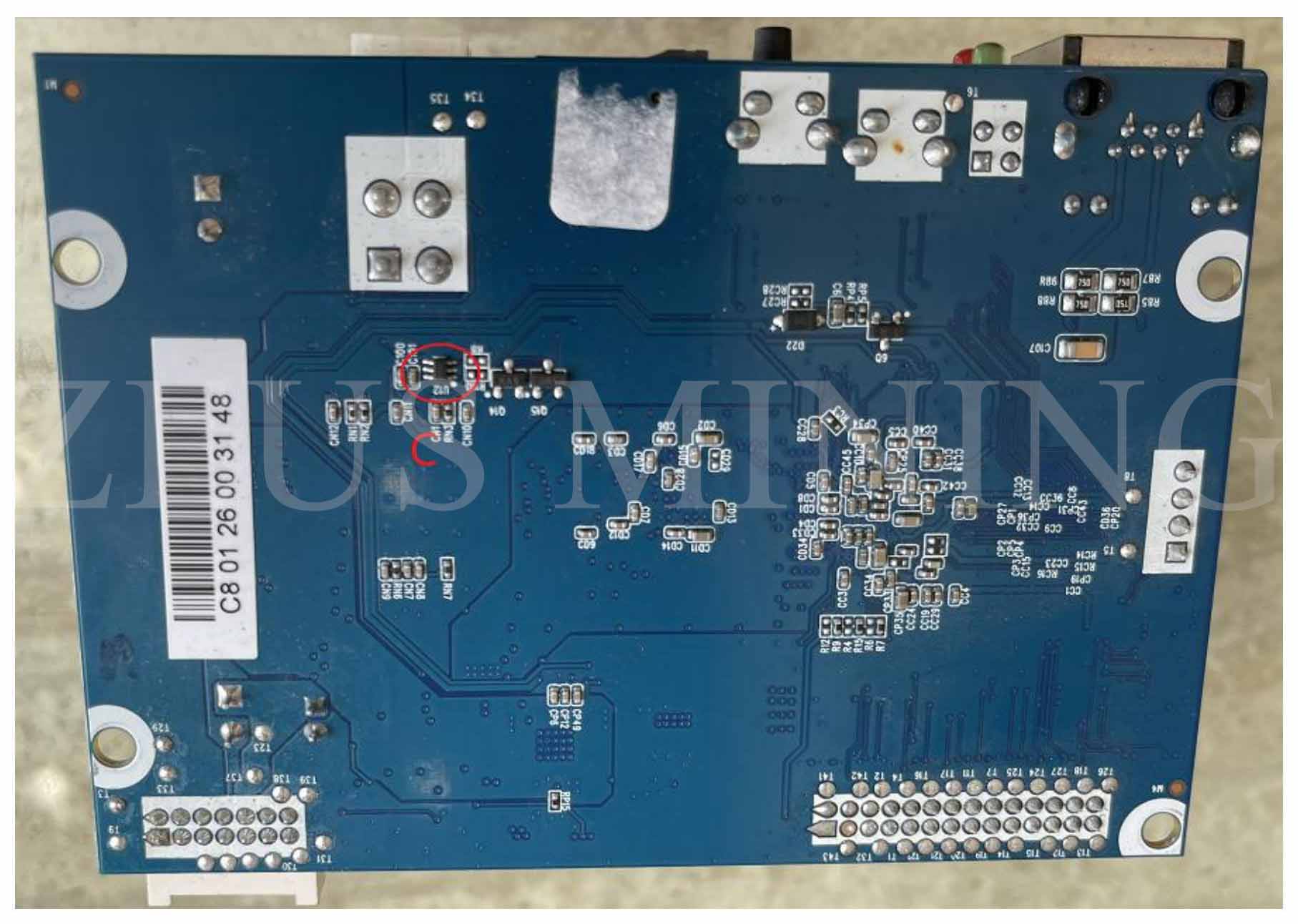
Pic 4 Back side C location
Step 2:Short circuit check and repair without power
1. Switch the multi-meter to the buzzer level and test whether there has a short circuit on the A / B / C / D / E / F / G location as below.
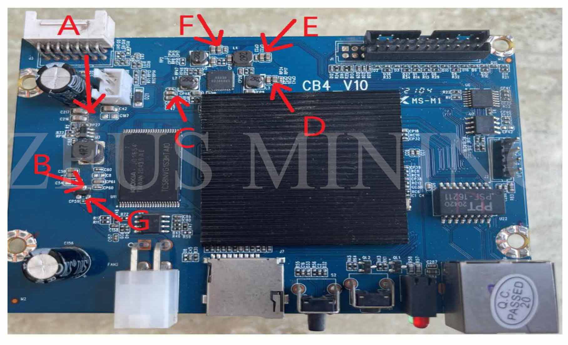
Pic 5 Test location as an arrow point
2. If there is a short circuit on A of Pic 5, it means U3 is most probably damaged; replace the U3 directly to repair, then test whether the short circuit issue is still there.
3. If there has a short circuit on B of Pic 5, there have 3 probables as below:
1st: U3 damage:
Remove the U3 and test whether the short circuit issue is still on B of pic 5; if no short, it means U3 is damaged; replace U3 directly to repair.
2nd: U2 damage
Remove the U2 and test whether the short circuit issue is still on B of pic 5; if there is no short issue, then it means U2 is damaged; replace U2 directly to repair.
3rd: U5 damage
Remove the U5 and test again to determine whether the short circuit issue is still on B of pic 5; if there is no short, it means U5 is damaged; replace U5 directly to repair.
4. If there has a short circuit on C of Pic 5, there have 2 probables as below:
1st: U5 damage:
Remove L2, test I of Pic 6; if the short issue is still there, it means U5 is damaged; replace U5 to repair it directly.
2nd: U1 damage:
Remove L2 and test H of Pic 6; if the short issue is still there, it means U1 is damaged; replace U1 to repair it directly.
5. If there is a short circuit at the D terminal in Pic 5, there are 2 possibilities as below:
1st: U5 damage:
Remove L3 and test J in Pic 6. If there is still a short problem, U5 is damaged. Replace U5 and repair it directly.
2ed: U1 damage:
Remove L3 and test K in Pic 6. If there is still a short problem, U1 is damaged. Replace U1 and repair it directly.
6. If there is a short circuit in E in Pic 5, there are 2 possibilities as below:
1st: U5 damaged:
Remove L4 and test L in Pic 6. If the problem is still short, U5 is damaged. Replace U5 and repair it directly.
2nd: U1 damaged:
Remove L4 and test M in Pic 6. If there is still a short problem, U1 is damaged. Replace U1 and repair it directly.
7. If F in Pic 5 has a short circuit, there are 2 possibilities as below:
1st: U5 damaged:
Remove L1 and test O in Pic 6. If there is still a short problem, U5 is damaged. Replace U5 and repair it directly.
2nd: U1 damaged
Remove L1 and test N in Pic 6. If there is still a short problem, U1 is damaged. Replace U1 and repair it directly.
8. If there has a short circuit on G of Pic 5, there have probably as below:
Remove L2, test G of Pic 5; if the short issue is still there, then it means U1 is damaged, replace U1 to repair it directly. If not short anymore, it means U2 is damaged, replace U2 to repair it.
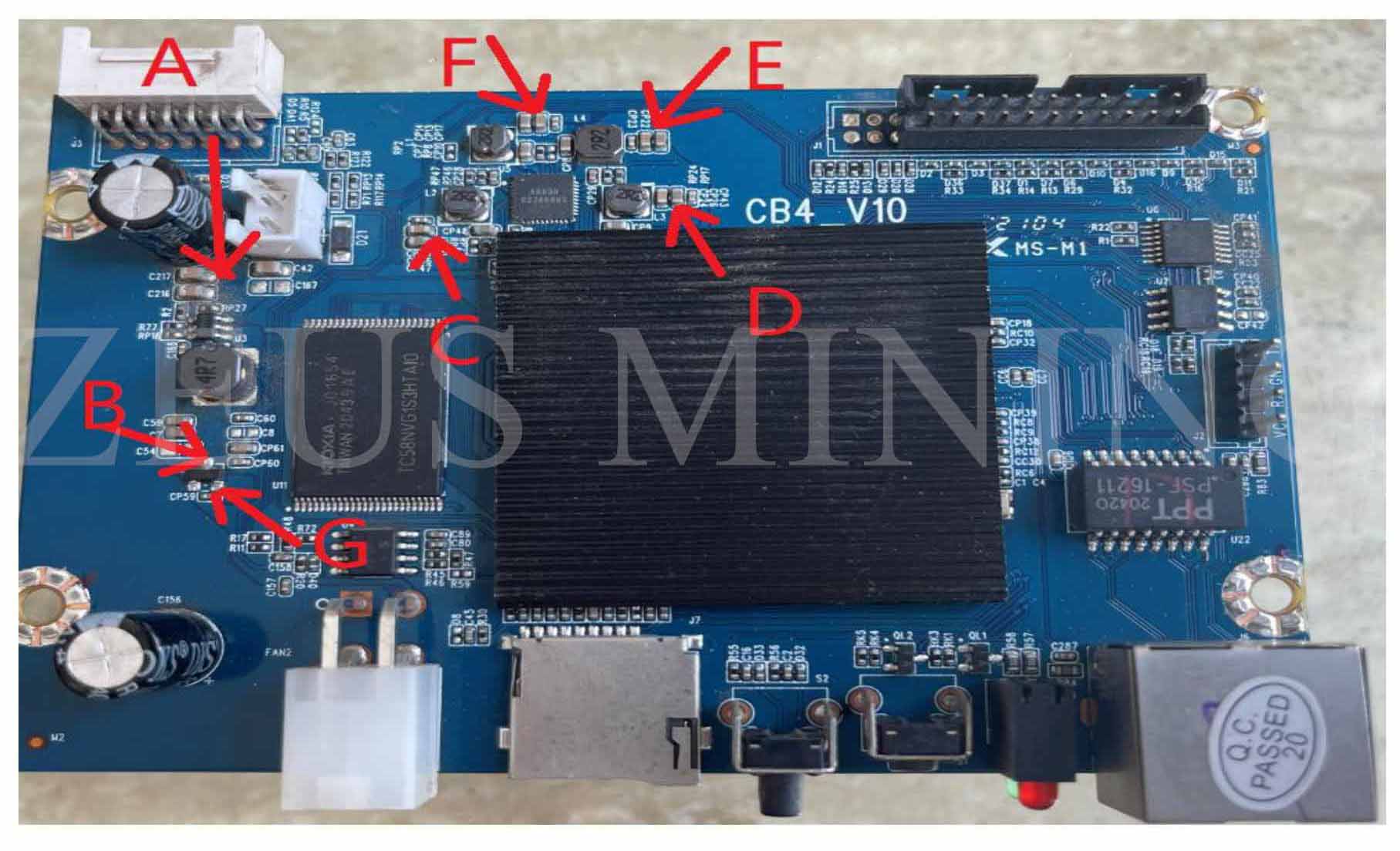
Pic 6 Test point after removing the inductance
Step 3:No short issue found on the above test, do test with power to further check and repair
1. After power on, test G of pic 5; if it’s not 1.8V (float more than 5%), the common value shows 0, 3.4V, 5V, etc. Then it means U2 has an issue and needs to replace U2 to repair.
2. If it’s 1.8V, flash the new program to check whether the board will work normally.
Above all, those are common issues that most probably happen for repair; if the board can’t be repaired by the above method, then it needs to be sent to the repair center.
Whatsminer CB4 V10 control board U2 U3 failure testing
Test Procedure:
1. Power on the control board only; connect the control board with PSU; remember to set the foam pad to prevent short circuits.
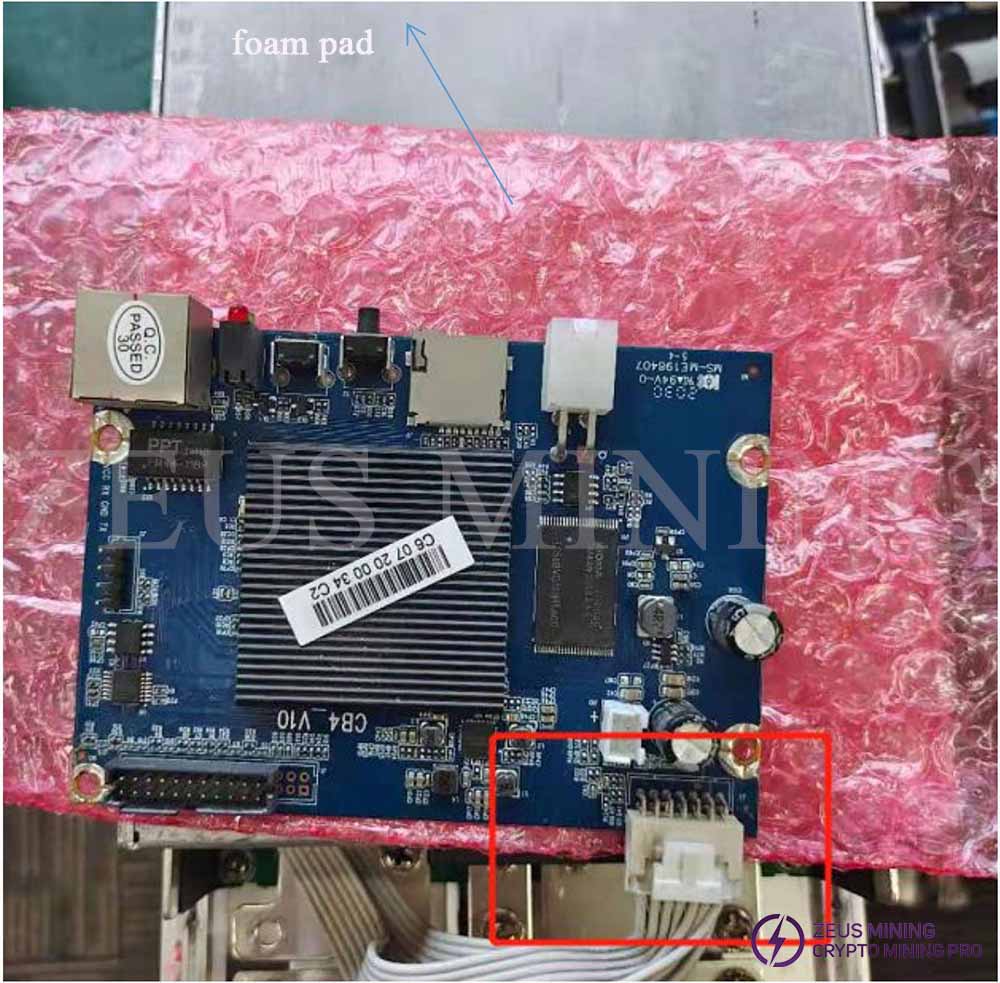
2. Set the multimeter to the “voltage” level.
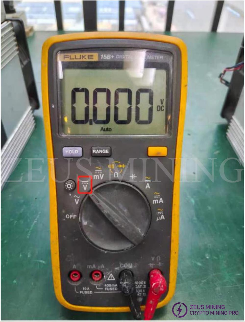
3. Test the input voltage of U2. One test lead is connected to the input pin of U2, and another to the SD card socket as below.
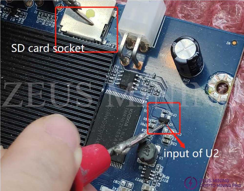
4. If it is not 5V(4.75V-5.25V can be accepted as a reasonable voltage of 5V), it means U3 is damaged and need to replace the U3.
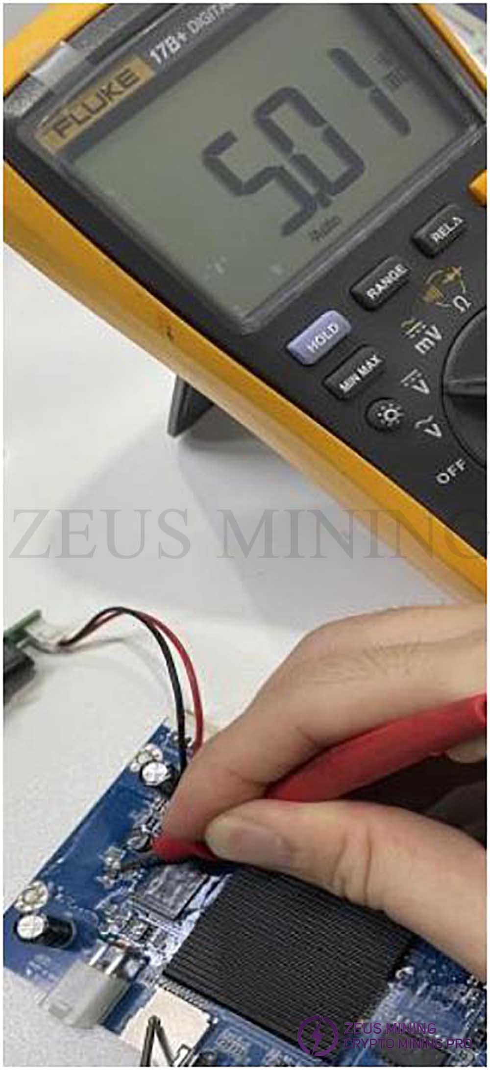
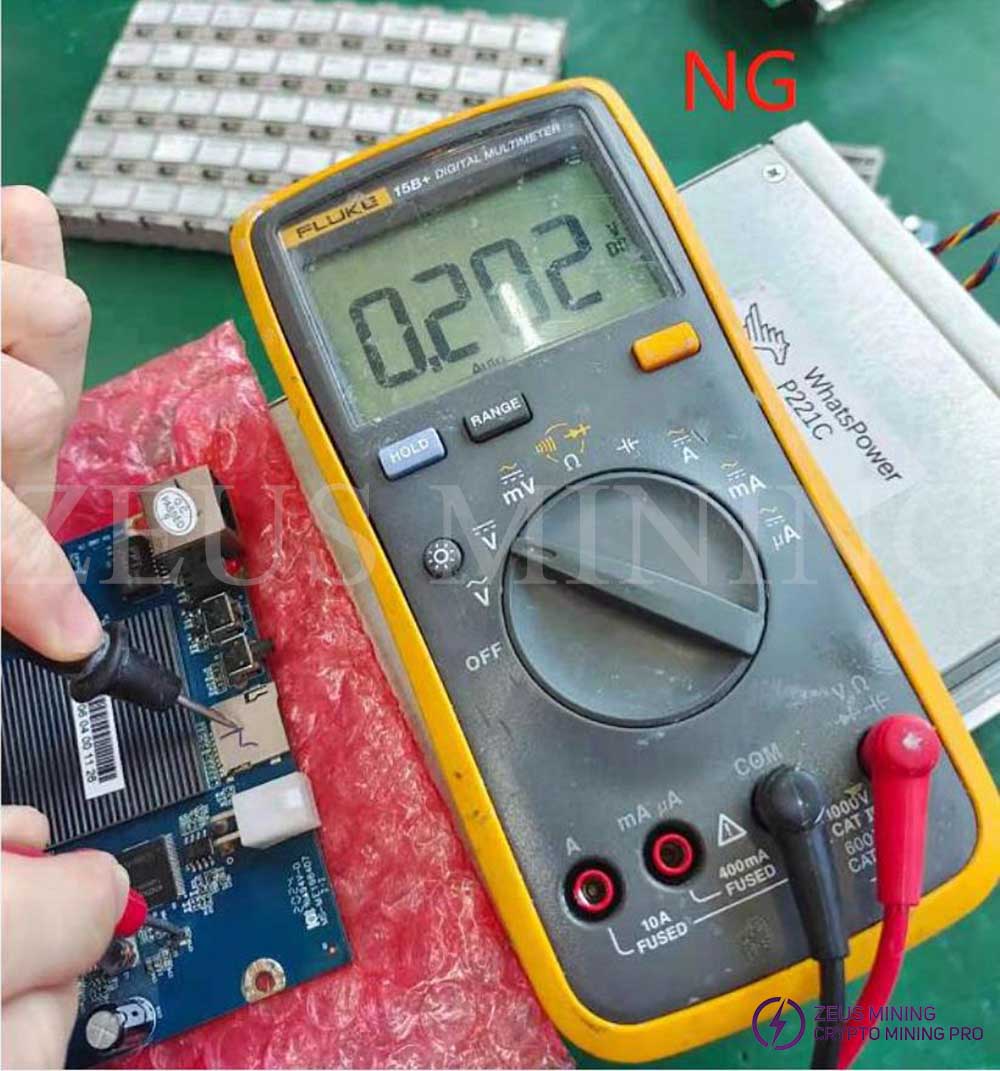
5. If it is 5V, then need to test the output of the voltage to check whether the output voltage is 1.8V, test the input voltage of U2, one test lead to the left pin which is closed to the CP59, another test lead to the SD card socket as below.
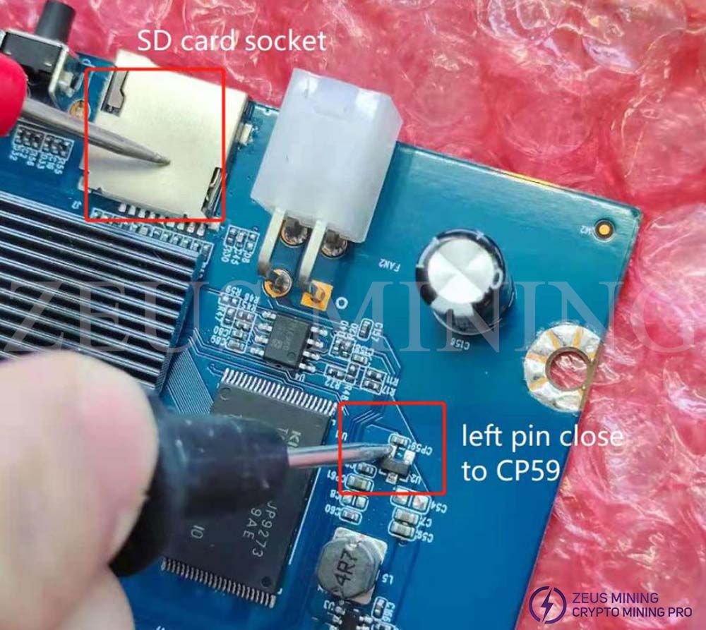
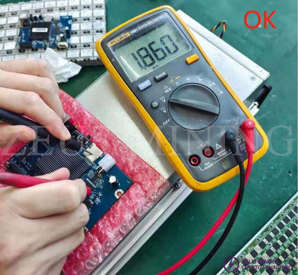
6. If the voltage is around 1.8V(1.71V-1.89V can be accepted as a reasonable voltage of 1.8V), then it means U2 is okay; if the voltage is much more different from 1.8V, it means U2 is a failure, need to replace the U2 component, as below shows.
Dear Customers,
Hello, April 4, 5 and 6, 2025 (GMT+8) are the traditional Chinese festivals - Qingming Festival. Our company will suspend shipments during these 3 days and resume shipments on April 7 (GMT+8). We are deeply sorry for the inconvenience. Thank you for your understanding and support.
Best wishes,
ZEUS MINING CO., LTD