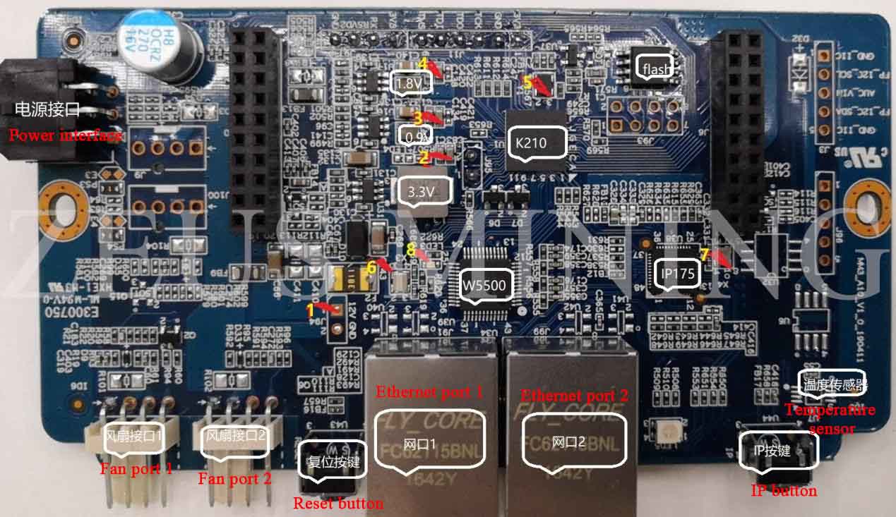


1. Introduction to the MM3 control board port
 2. MM3 control board maintenance process
1) First measure whether the ground impedance of the 4 voltage points is abnormal (Fluke 15B + multimeter black test lead to GND, red test lead to each test point): 12V (yellow mark 1) impedance is more than 2KΩ, 3.3V (yellow mark 2 capacitor C83) impedance is about 4.2KΩ, 0.9V (yellow mark 3 capacitor C419) is about 100Ω, 1.8V (yellow mark 4 capacitor C420) impedance is about 5.4k. If the measured impedance is abnormal, always check the corresponding power chip, load and capacitor. For example, the 3.3V load has K210, W5500 (COMW5), IP175, the 0.9V load is K210, and the 1.8V load has K210 and flash. The judgment method can be taken by disconnecting the inductors (3.3V power supply inductor L3, 1.8V power supply inductor L5, 0.9V power supply inductor L4) to see if the resistance on the left and right sides of the inductor is normal.
2) After the impedance is normal, use the Fluke 15B + multimeter to measure the voltage at points 2, 3, and 4 marked red. If the voltage is abnormal, check whether the circuit around the corresponding 6-pin power chip is abnormal.
3) Power on after no abnormality in the voltage test, measure whether there is a 26M square wave at 5 places (pin3 of Y1), and whether there is a 25M sine wave at 6 places (pin1 of X3) and 7 (pin1 of X4) (Measure when there is an oscilloscope, go directly to step 4 without an oscilloscope).
4) If the previous program cannot be started under normal circumstances, judge whether the program is abnormal or not, and judge by re-programming the program. If there is a problem with programming, check whether the flash and K210 are damaged.
5) The functional problems of starting the normal MM3 board:
a. The green light of LED3 on the left side of W5500 (yellow mark 8) cannot be lit. Check the related circuits of W5500 and IP175;
b. The temperature reading of the air inlet is abnormal, and the temperature sensor chip and related circuits are checked;
c. A particular HASH starts abnormally, check whether the impedance of the signal (CI, RI, DI, CO, RO, DO, etc.) at the interface with the hash is abnormal, whether the PCB is disconnected and whether the K210 is soldered;
d. If the fan speed is abnormal, check the fan_pwm and fan_speed signals at the fan interface and related circuit problems (resistance and capacitance near the fan interface);
e.2 The network port is plugged in, and the cable is short-circuited. Normally, the green LED lights of the two network ports are lit. If they cannot be lit, check the related circuit of IP175.
Dear Customers,
Hello, April 4, 5 and 6, 2025 (GMT+8) are the traditional Chinese festivals - Qingming Festival. Our company will suspend shipments during these 3 days and resume shipments on April 7 (GMT+8). We are deeply sorry for the inconvenience. Thank you for your understanding and support.
Best wishes,
ZEUS MINING CO., LTD