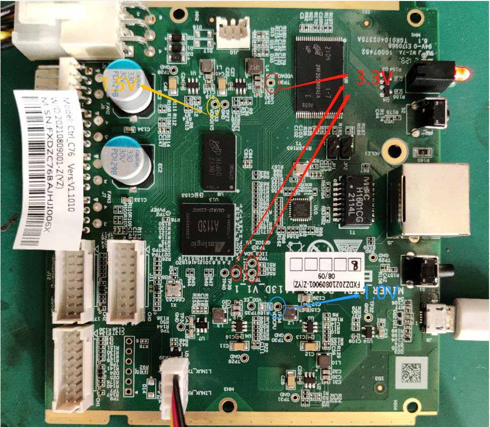


The amlogic board structure is as shown below. U2, U3, U4, and U6 are powered by 12V.
(1) Among them, U2 transfers out 5V, and 5V is supplied to U14 for use;
(2) U3 transfers out about 1.0V from VDDCPU;
(3) U4 transfers out VDDEE about 1.0V;
(4) U6 outputs 3.3V;
(5) U1 is powered by 3.3V and then converted to 1.5V;
(6) U7 is powered by 3.3V and then converted to 1.8V; both of them directly supply power to U13.

For details on burning, please refer to the burning instructions. When programming this control board, the key selected is OTP.
The burning mode is OTP mode: OTP (One Time Programable) is a memory type of MCU, which means one-time programmable: after the program is burned into the IC, it cannot be changed or cleared again.
Note: A sudden power outage or less than 30 seconds during the OTP opening process will cause the control board to fail to open the OTP function and the control board will not start (not connect to the Internet). U1 (control board main control IC BGA) needs to be replaced. The replaced U1 cannot be used again. U1 cannot be used on other series of models if the OTP function is enabled on the control board.
1) Failed to read the IP; there is a high probability that the IP cannot be found due to abnormal operation.
Check the appearance and welding condition of the network port, network transformer T1, and CPU; measure whether the above voltage parameters are normal.
2) The whole miner cannot be upgraded
Check the appearance and welding condition of the network port, network transformer T1, and CPU.
3) The whole miner fails to read the hash board or lacks chain
A. Check the cable connection status;
B. Check the parts corresponding to the chain on the control board;
C. Check the wave soldering quality of the header pins and the resistance around the plug-in interface.
4) Failed to burn or connect
A. Check whether the USB cable has data connection function;
B. Check the micro USB interface welding on the control board;
C. Check U14 welding, check U2 welding and 5V voltage output.