


In fact, Innosilicon and Antminer use similar circuit structures, and their principles are roughly the same. We can use the Antminer repair method to repair Innosilicon.
This article takes Innosilicon T1 as an example to briefly introduce its circuit structure.
T1 consists of 21 voltage domains connected in series, each voltage domain has 3 chips, and there are 63 T1558 chips on the entire board.
The whole circuit board has two 12M clock crystals, they are connected in series from the first chip to the 30th chip, and the other is transferred from 31 chips to the last chip
Its transmission signal is: CLK-SCK-CS-DI-DO
The red arrow indicates the direction of the CLK signal
The yellow arrow shows the direction of the SCK signal
The green arrow shows the direction of the CS signal
The blue arrow shows the direction of the DI signal
Purple arrow shows DO signal direction
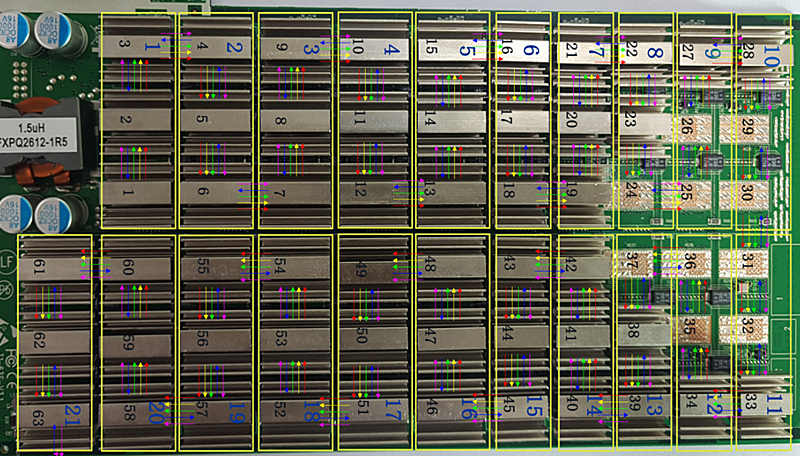
It can be seen from this: "CLK-SCK-CS-DO" is sequential transmission, "DI" is reverse transmission
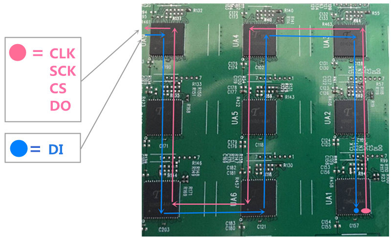
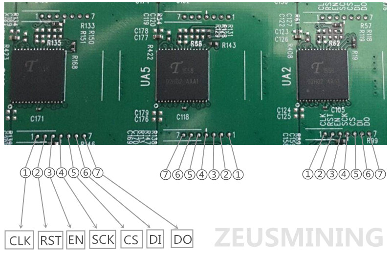
Each chip has 7 test points, arranged in order of 1 - 7, they are: CLK - RST - EN - SCK - CS - DI - DO
Please note: every other set of chips is arranged in reverse order, please measure according to the circuit board logo
Chip schematic diagram:
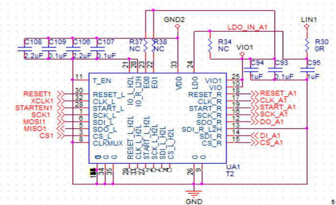
Interface definition diagram:
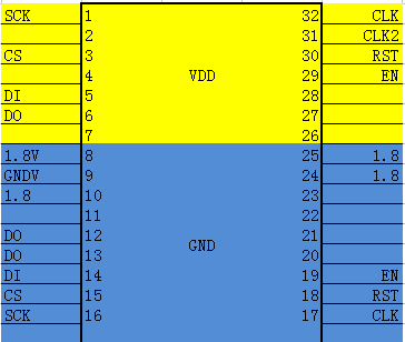
For more instructions, please download the "Innosilicon miner hash board repair guide":
Click to download "Innosilicon miner hash board repair guide"
Related maintenance tools:
ANLIXIN-858D High Quality Hot Air Gun Desoldering Gun
ANLIXIN-936A High Quality Electric Iron
Fluke 15b + f15b + digital multimeter instrument with LED backlight
Click to see more miner maintenance tools