

To facilitate the correct use of the AntSpace HK3 V2 container, we have compiled some precautions for the electrical wiring of the AntSpace HK3 V2 container, hoping to help you.
1. Since there are two 500kW power distribution cabinets inside the equipment, to ensure the equipment's safe and stable operation, two three-phase five-wire cables with a load of 500kW should be prepared on-site in advance (no specifications are specified).
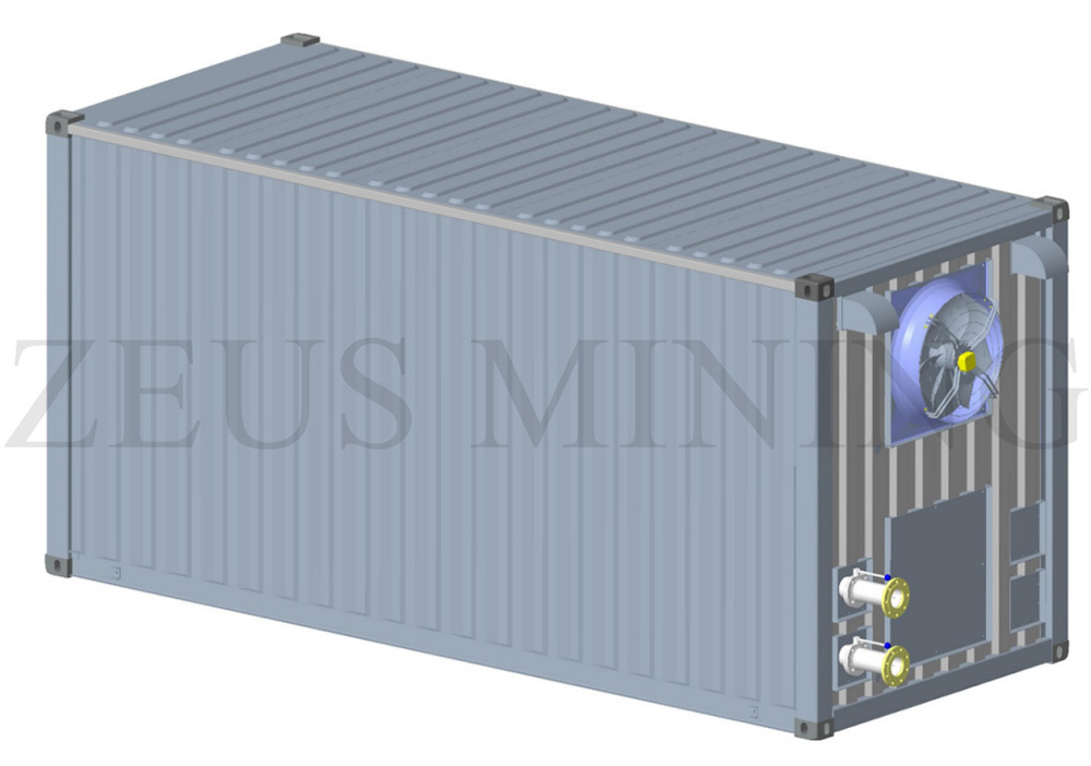
2. The cables are connected from the upper two openings on one side of the container exhaust fan. The specific positions are shown in Figure 1 (Note: the rain cloth and rain cover in the accessories need to be used for protection). The cables are connected from the top junction boxes of the two power distribution cabinets, extend to the corresponding copper bars, and are fixed with screws.

Figure 1: Cable entry hole
3. There are grounding studs on both sides of the container, and the power distribution cabinet should also be reliably grounded. Therefore, choose to ground both the container shell and the power distribution cabinet shell.
4. When leaving the factory, the phase sequence of the equipment has been determined. Therefore, after the equipment arrives at the site, it only needs to adapt to the phase sequence of the on-site substation.
The specific operations are as follows: connect the three-phase power of the substation to the power distribution cabinet, power on the electric control box, and observe whether there is a power failure; if there is a power failure, please adjust the phase sequence connected to the electric control box; if there is no failure, then can operate normally.
5. Since the cooling tower and the container are separated, there are three cooling fans, a spray pump, and a liquid level sensor above the cooling tower. After the cooling tower and container positions are determined, 4 motors and a sensor need to be wired.
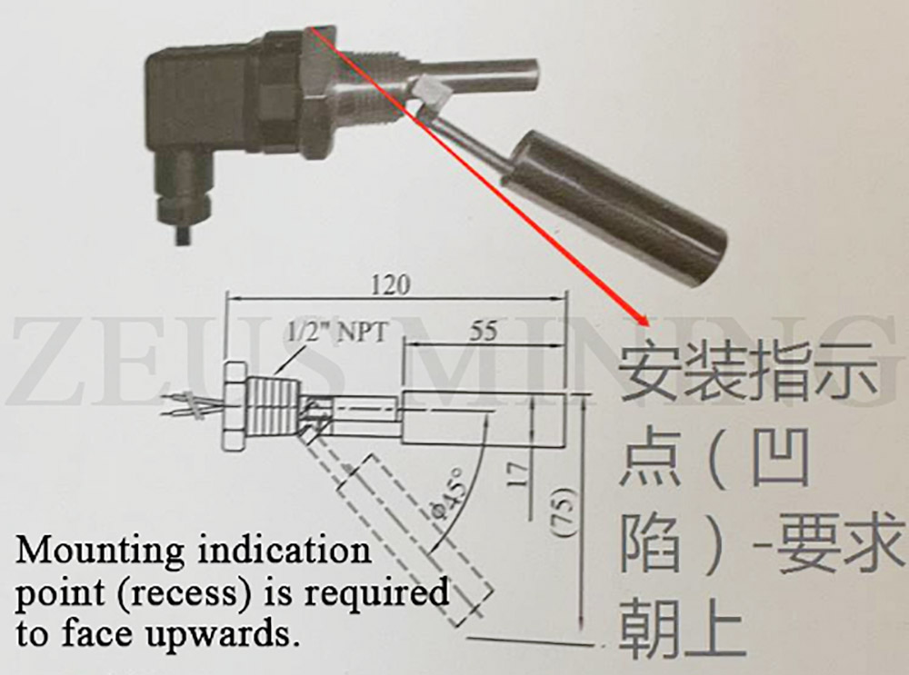
a) The liquid level sensor requires the indicating installation point (depression) to be upward, as shown in Figure 2. Therefore, the 5-way wire has been reserved.

Figure 2: Liquid level sensor
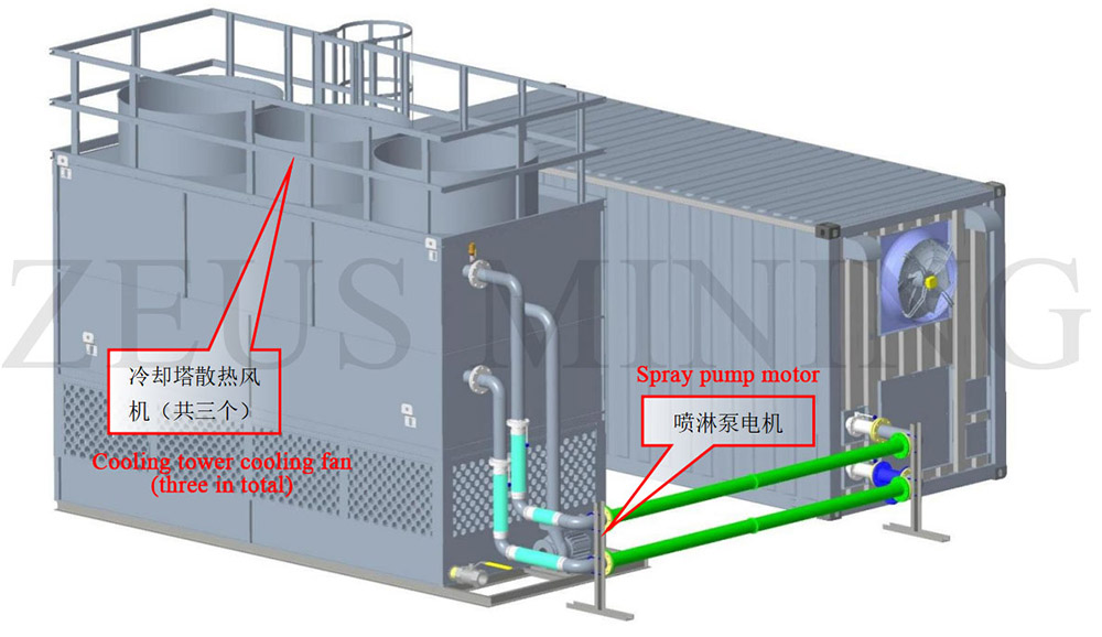
b) The order of the three cooling fans is not specified, but the wiring sequence is U, V, and W (from left to right). The position of the cooling fans is shown in Figure 3. The top and side of the cooling tower are reserved for cable slots, and the cables need to be arranged along with the cable slots. The wiring sequence for the spray pump is also U, V, and W (from left to right).

Figure 3: Location map of cooling tower cooling fan
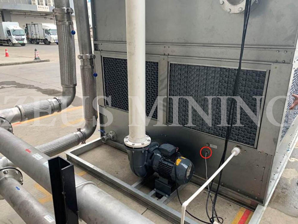
c) The position of the liquid level sensor has been reserved, find the NPT1/2 nut and gasket from the cooling tower spare parts box, remove the cooling tower air inlet grille, install the liquid level sensor from the inside out, and install the liquid level sensor as shown in the figure below 4 shown.

Figure 4: Schematic diagram of liquid level sensor installation
Note: This is the water-cooled container parameter of the AVIC 1.3 version. If your product is from other manufacturers or versions, it may differ slightly from this parameter. This parameter is for reference only.
Dear Customers,
Hello, April 4, 5 and 6, 2025 (GMT+8) are the traditional Chinese festivals - Qingming Festival. Our company will suspend shipments during these 3 days and resume shipments on April 7 (GMT+8). We are deeply sorry for the inconvenience. Thank you for your understanding and support.
Best wishes,
ZEUS MINING CO., LTD