


System/tank rehydration steps:
1. The exterior needs to be equipped with a self-priming pump. When adding liquid for the first time, the self-priming pump needs to inject liquid into the pump head; find the liquid filling port outside the container (at the side door of the container), plug in the hose, clean it, and the external coolant is connected to the suction port of the self-priming pump; (see Figure 1)
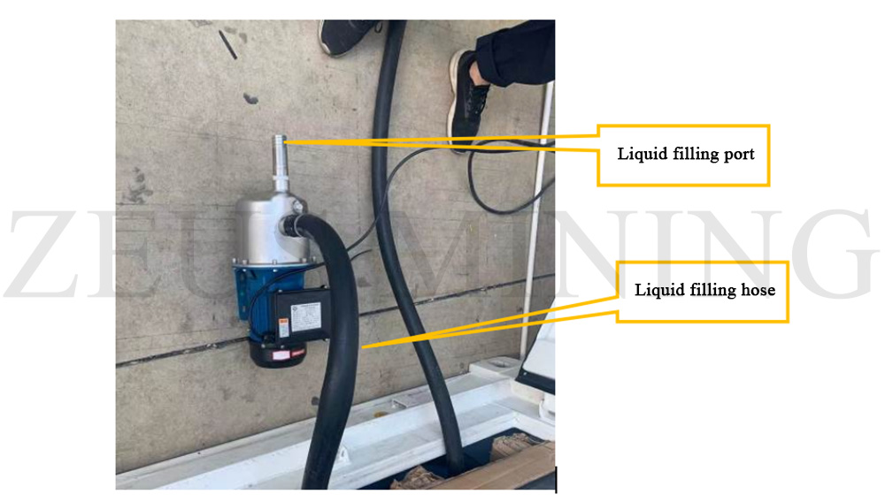
Figure 1 Pumping station - filling hose
*Note: Self-priming pump recommendation and reference: rated flow 3m3/h, rated head 30m, output power 1kW, electrical system 380V/50Hz;
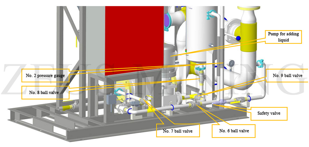
Figure 2 Pumping station - filling valve
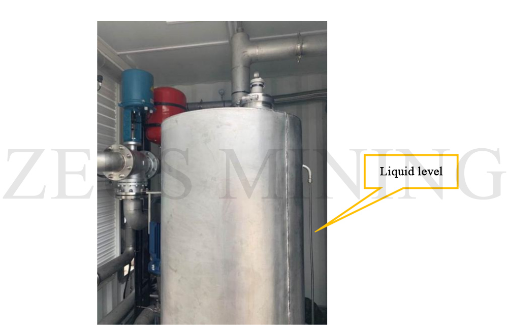
Figure 3 Pumping station - level gauge
2. Close the No. 8 ball valve and No. 6 ball valve shown in Figure 2, open the No. 7 ball valve, and click "Rehydration Pump" on the touch screen interface to open (this liquid rehydration pump is a pump for dual purposes, that is, it is responsible for supplying fluid to the system and the water tank. ) (when the valve handle is parallel to the pipeline, it is in the open state, and when the valve handle is perpendicular to the pipeline, it is in the closed state);
3. When the system is filled with liquid, when the static pressure reaches 7bar (refer to Figure 4, the reading on the touch screen), the circulating pump can be turned on for 10s (the infusion pump does not need to be stopped), and then the circulating pump can be stopped;
4. Continue to add liquid; repeat this twice to ensure that 3~1.5 tons of coolant are added;
5. Stop adding liquid when the static pressure reaches 1 bar (observe the reading of the pressure sensor on the main interface, see Figure 4 below);
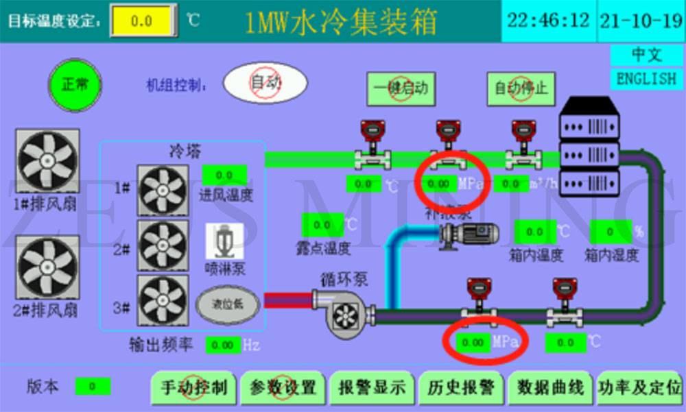
Figure 4 Pressure sensor readings on the main interface
6. Then turn on the circulating pump again to circulate the medium in the system to ensure that several exhaust valves are open;
7. Then open the No. 6 ball valve, close the No. 7 ball valve, click "Rehydration Pump" on the touch screen interface to open, add liquid to the water tank, and stop adding liquid when the liquid level gauge in the water tank reaches more than 2/3 (see Figure 3 for the position of the liquid level gauge).
8. Close the No. 9 ball valve and No. 6 ball valve outside the container, and open the No. 8 ball valve and No. 7 ball valve;
9. When the system is running, use a wrench to slowly unscrew the exhaust port plug of the circulating pump counterclockwise and manually exhaust the circulating pump (G1/2 external thread) until the exhaust port of the circulating pump continuously flows out coolant. Please turn off the circulator pump exhaust plug by turning it counterclockwise. (See Figure 5 for the exhaust port of the water pump)
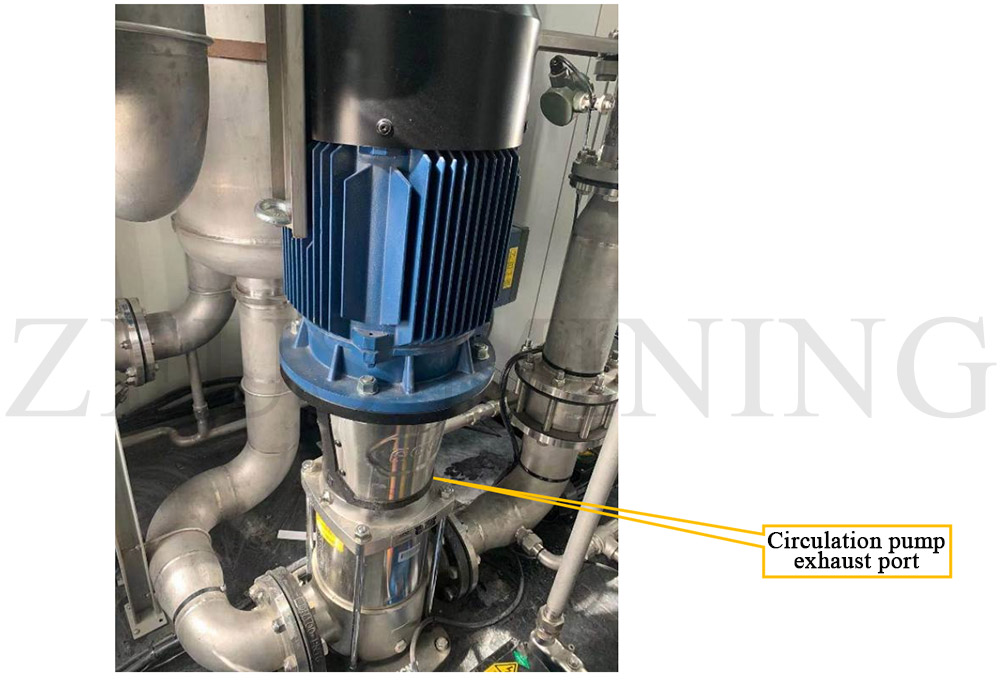
Figure 5 Pumping station - exhaust port of circulating pump
*Note: This is the water-cooled container parameter of the AVIC 1.3 version. If your product is from other manufacturers or versions, it may differ slightly from this parameter. This parameter is for reference only.
Dear Customers,
Hello, April 4, 5 and 6, 2025 (GMT+8) are the traditional Chinese festivals - Qingming Festival. Our company will suspend shipments during these 3 days and resume shipments on April 7 (GMT+8). We are deeply sorry for the inconvenience. Thank you for your understanding and support.
Best wishes,
ZEUS MINING CO., LTD