

The oscilloscope UTD2102CEX+ can be used for hash board repair. We can quickly determine whether the ASIC chip signals are normal through the oscilloscope, find faults faster and deal with them to achieve the purpose of repair. It provides richer triggering methods, 34 kinds of automatic parameter measurements, and standard mathematical operation functions. It optimizes panel operation, meets the measurement needs of complex signals, and greatly improves work efficiency.
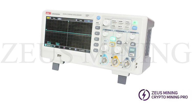
Steps to set up the oscilloscope UTD2102CEX+:
1. Start the oscilloscope: Press the power switch on the top of the oscilloscope.
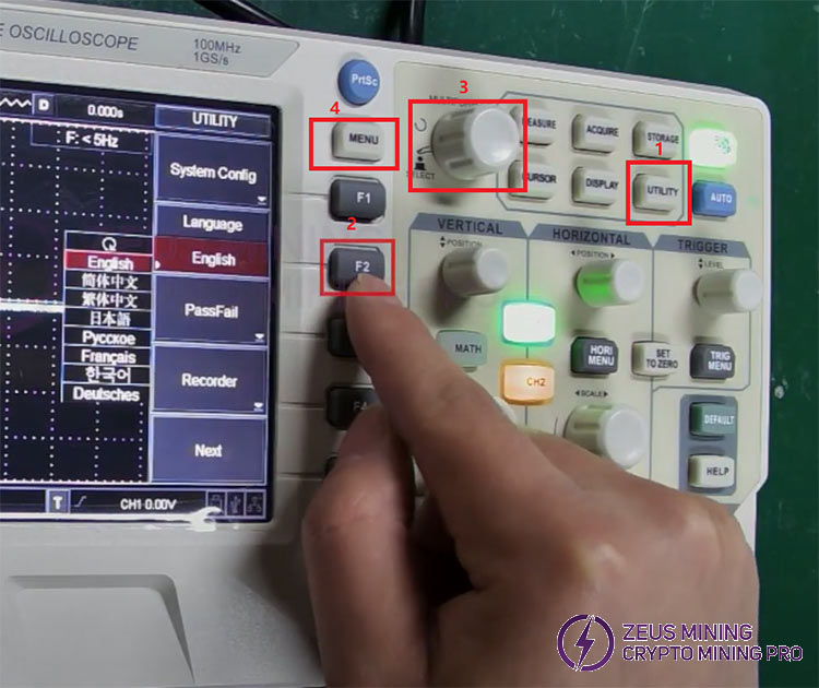
2. Language selection: Press the "UTILITY" button, then press the "F2" button and rotate the knob next to the "MENU" button to select the language. Finally, press the knob button to confirm the selection and press the "MENU" button to return to the main interface.
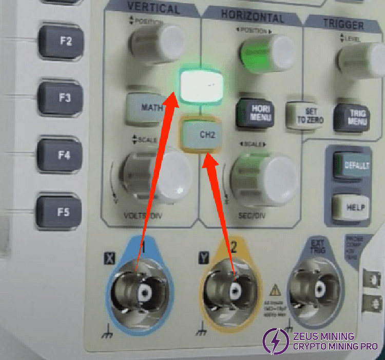
3. Channel selection: The blue channel corresponds to the "CH1" button, and the yellow channel corresponds to the "CH2" button. Press once to turn on the channel, and press twice to turn off the channel.
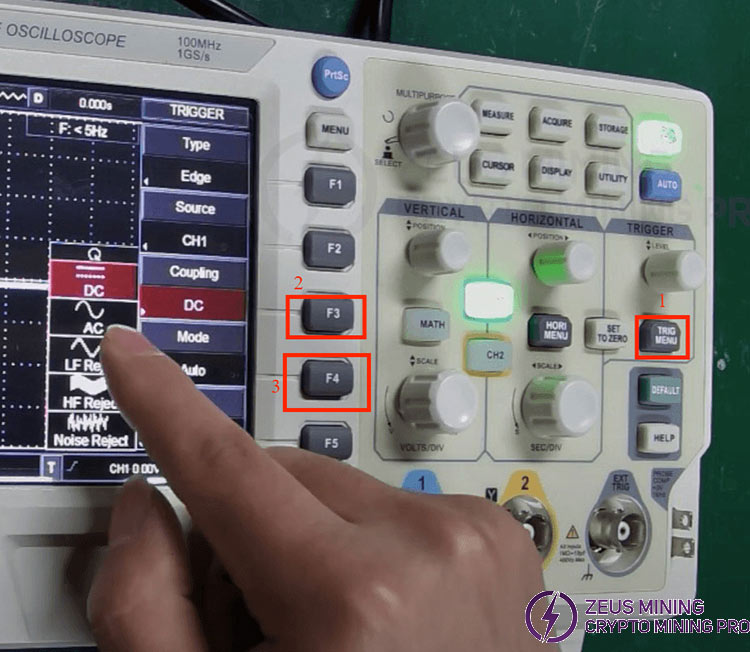
4. Mode selection: Press the "TRIG MENU" button, then press the "F3" button, and use the knob to adjust to "AC" mode. Finally, press the "F4" button and use the knob to adjust to "Normal" mode. (After selecting the mode, press the knob button to confirm the setting)
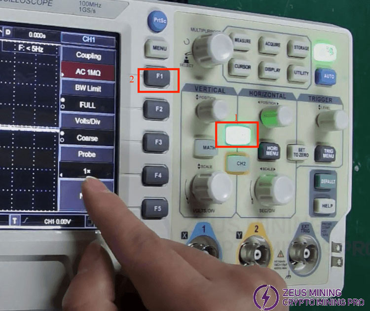
5. Channel mode setting: Press the corresponding "CH" button of the channel you just selected, then press the "F1" button and use the knob to set it to "AC" mode. The "1x" on the screen represents the default value of the oscilloscope is "1x", remember this mode and press the "MENU" button to return.
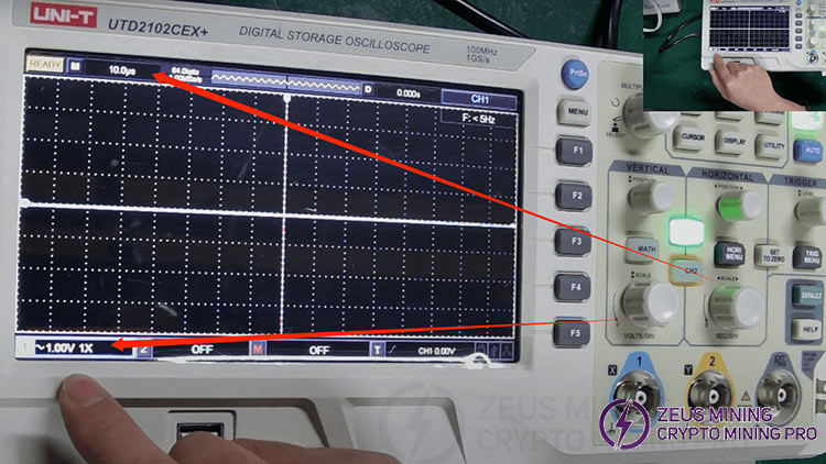
6. Amplitude and frequency settings: The knob above the blue channel corresponds to the amplitude, and the knob above the yellow channel corresponds to the frequency. Rotate the knobs to set the amplitude and frequency to 1V and 10μs. (The amplitude and frequency can be adjusted for different types of hash boards, and this setting is suitable for most hash boards)
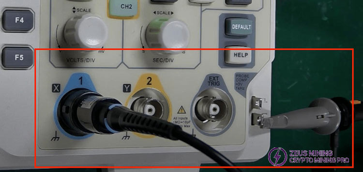
7. Insert the oscilloscope probe into the selected channel, tighten it clockwise, and hang the other end of the probe on the nearby hook. So far, the oscilloscope setup is complete.
Steps to use the oscilloscope UTD2102CEX+:
1. Tools needed (it needs to be used with other tools): ASIC miner test fixture (such as PicoBT tester, APW3+ power supply, double-row cooling fan, adjustable voltage PSU, oscilloscope UTD2102CEX+
2. On the adjustable voltage PSU, set the voltage value that matches the hash board to be tested and connect the relevant cables.
3. Clamp the oscilloscope probe clip onto the negative terminal of the hash board. (Note that the clamp must be tightened securely. If the clamp loosens during testing, it may damage the oscilloscope.)
4. Place the hash board on the cooling fan, turn on the PicoBT test fixture, and press the test button.
5. Ensure that the oscilloscope probe is set to X1 (consistent with the oscilloscope setting), and toggle the orange button if needed.
6. Finally, use the oscilloscope probe to measure the signal waveforms on the hash board, and observe the different waveforms on the screen to determine whether the ASIC chip signals are normal.
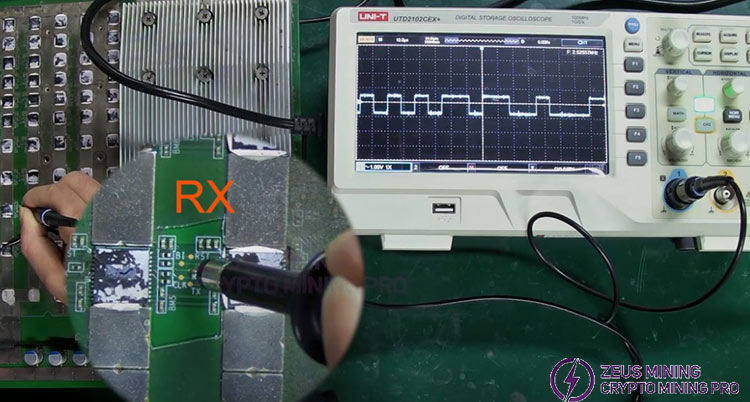
These are the steps and methods for using the oscilloscope UTD2102CEX+.
Note:
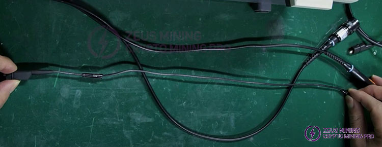
When using the oscilloscope probe, the original clip cable is too short and inconvenient to test. We can cut the cable and use a cable of similar thickness to pass it, which is more convenient to test the chip signal at any position on the hash board.
