


The Avalon debug D-signal shorting board, also known as the Avalon faulty ASIC chip finder, supports the Avalon A12 series, A11 series, and A10 series. When testing a single Avalon hash board, if the test fixture reports 0 or incomplete numbers, this tool can quickly find and locate the fault point, regardless of whether the C signal and CK signal are normal.
Taking the Avalon A1047 hash board test as an example, today we will mainly introduce how to use this board to short the D signal:
I. Understand the interfaces on the short-circuit board before use
A: Interface for connecting to the test fixture; B: 12V DC power interface; C: interface for connecting to the hash board; D: switch button.
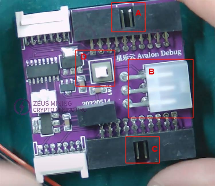
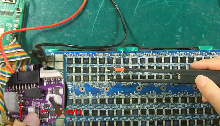
When we press the switch up, it will enter the normal test mode. When we press the switch down, it will enter the shorting mode, allowing us to short the D signal to find the faulty chip. D signal can also be used as a bridge to connect the hash board and the test fixture.
II. Prepare accessories and tools
Screwdriver, shorting probe, two data cables for connecting the D signal from the hash board to the test fixture, main control board for the test fixture, footswitch, data cable for detecting the A10 series, hash board power cable, USB cable connecting the test fixture to the computer, 12V DC power supply (for powering the fixture and D-signal shorting board), Avalon A1047 hash board, cooling fan.
III. Connect all cables
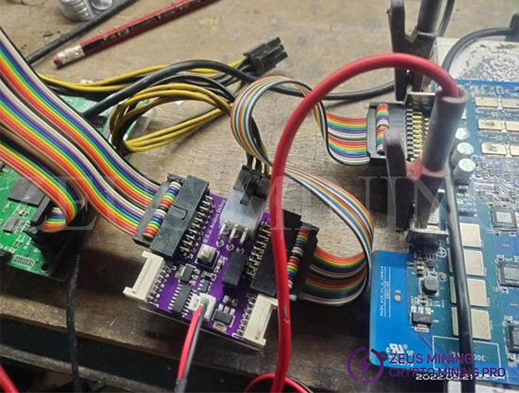
1. We will first connect the cables and insert the short circuit probe interface into the shorting board.

2. Insert one end of the ribbon cable into the shorting board and install the other end onto the hash board.
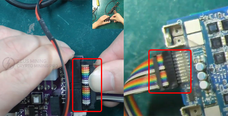
3. Use a screwdriver to fix the power cord ribbon interface to the test fixture, fix the "+" sign to the positive pole, and install the "-" sign to the negative pole.

4. We are using the A10 series hash board for demonstration, so we need to toggle the switch to the A10 position. Then press the white switch upwards.
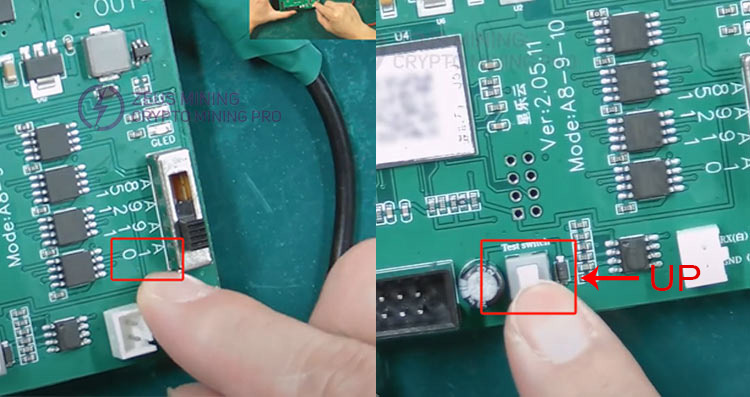
5. Connect the black wire of the double-headed USB cable to GND and the white wire to RX. Insert the USB interface to the computer.
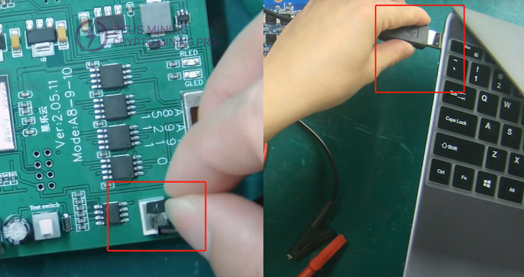
6. Insert one end of the ribbon cable into the test fixture interface and connect the other end to the shorting board.

7. Install the foot switch to the test fixture, and both interfaces on the fixture need to be connected to a 12V DC power supply.
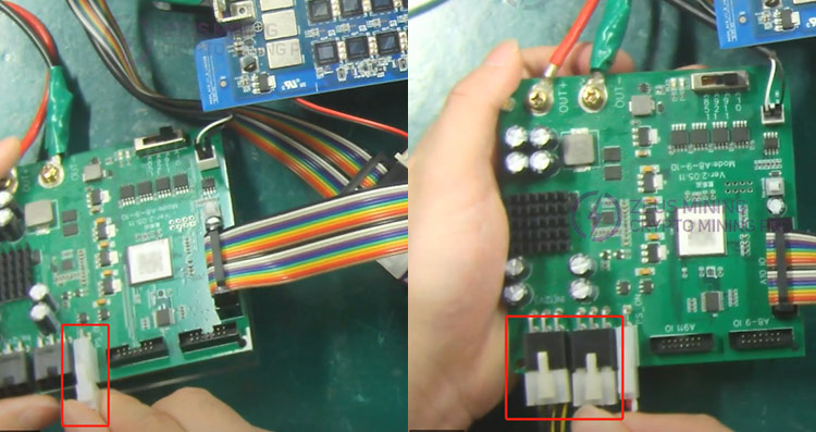
8. Connect the D signal shorting board to a DC power supply.
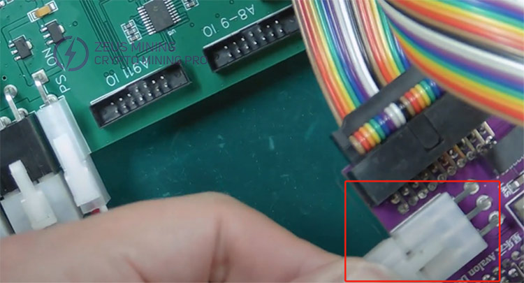
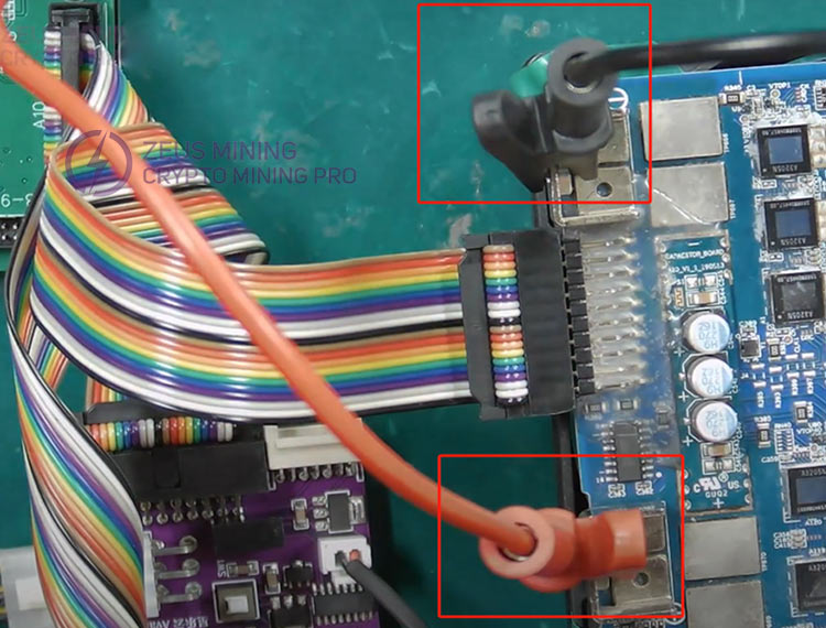
9. Correctly install the positive and negative terminals of the power cable onto the hash board.
10. Turn on the cooling fan switch to dissipate heat for the hash board.
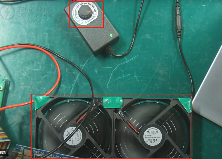
Detailed diagram of shorting board connections:
IV. Use the test fixture to test the hash board
1. Press the white switch on the test fixture and press the white switch on the shorting board up to run the serial port software.

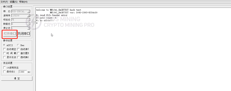
2. Click to open the serial port and press the foot-switch. The test display shows: asic count: 0, indicating 0 ASIC chip was found.
3. Now we have shorted the D signal of the chip. At this time, we need to press the white switch on the shorting board down again to enter the measurement mode.
4. Here we need to use the shorting probe. The "-" side is the negative pole, used to connect to the negative pole of the chip's current domain to be tested. "+" is the positive pole, used for the chip's D signal test point. Then step downthe footswitch.
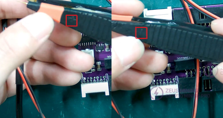
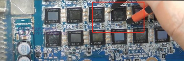
5. Short the D signal output from the A16 chip, and the test fixture displays an asic count of 10. Note that the correct chip count is 16-6=10, as there are no chips in the first 6 A1-A6 positions. The number reported in the log at this time is the same as the number of chips before the short signal, indicating that the first 10 chips are normal.
Avalon single board test display: missing chips
As shown in the figure:
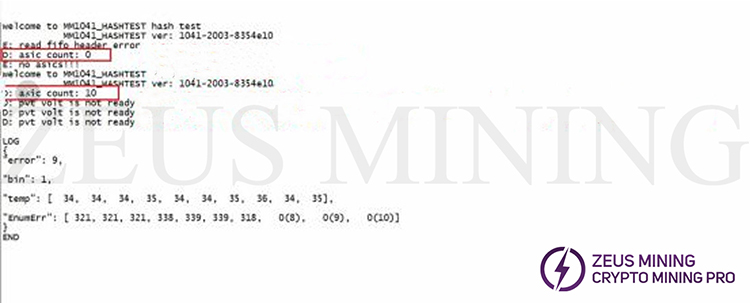
6. If the faulty chip is not found, we need to continue to short-circuit the D signals of the chips in turn to locate the faulty chip and repair it.
Avalon debug D signal short circuit board can help maintenance personnel quickly locate faulty chips, thereby shortening maintenance and downtime.
Dear Customers,
Hello, April 4, 5 and 6, 2025 (GMT+8) are the traditional Chinese festivals - Qingming Festival. Our company will suspend shipments during these 3 days and resume shipments on April 7 (GMT+8). We are deeply sorry for the inconvenience. Thank you for your understanding and support.
Best wishes,
ZEUS MINING CO., LTD