


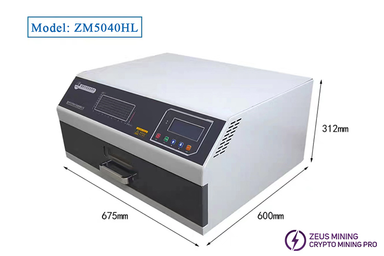
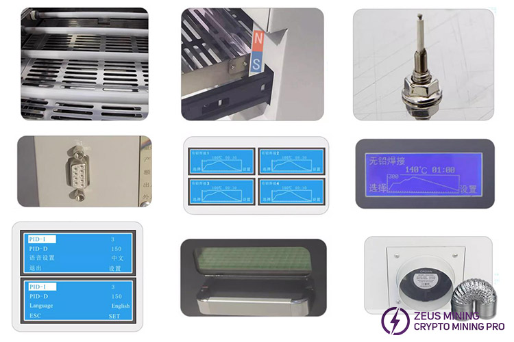
The ZB5040HL reflow oven is a desktop reflow equipment specifically designed for SMT and other product repairs, which can be used for the soldering of components on ASIC miner hash boards. It employs efficient far infrared heating and thermocouple temperature measurement, coupled with microcomputer controlled precise temp control, ensuring uniform and adjustable temperatures. The equipment is capable of automatically detecting faults and reporting them, integrating reflow, repair, and drying functions into one unit. Its circuits are efficiently integrated and have excellent temp maintaining performance, and the overall design is optimized in performance, structure and operation.
I. Overview of installation precautions
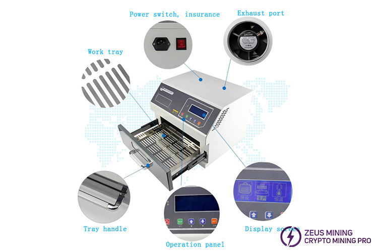
The equipment should be installed in a location that facilitates exhaust venting and equipped with a 15A three prong socket to ensure reliable grounding. The exhaust pipe should be made of 100mm diameter aluminum tubing, with the outlet positioned more than 1 meter above the machine and a total length not exceeding 1.5 meters. Do not install an exhaust fan at the end. The mica pad inside the drawer must not be removed, and no flammable liquids should be placed above it. Initial use of the equipment may emit an odor, which is normal and will dissipate over time. When not in use, please turn off the power switch. For long term storage, disassemble and store the machine in its original packaging to prevent continuous operation of the main control board.
II. Role and functions of temp profiles
The drawer type reflow oven has five temperature sections, simulating a tunnel oven, and each temp section is designed to meet different circuit board soldering requirements. The preheating section removes moisture, stress and residual gas; the heating section activates the flux and removes oxides; the soldering section realizes SMT soldering, which requires precise temperature control to prevent component damage; The heat preservation section ensures the solidification quality of the solder and avoids rough crystallization; the cooling section accelerates the cooling process for easy operation, usually to a temp that is not hot to the touch.
III. Understanding keypad functions
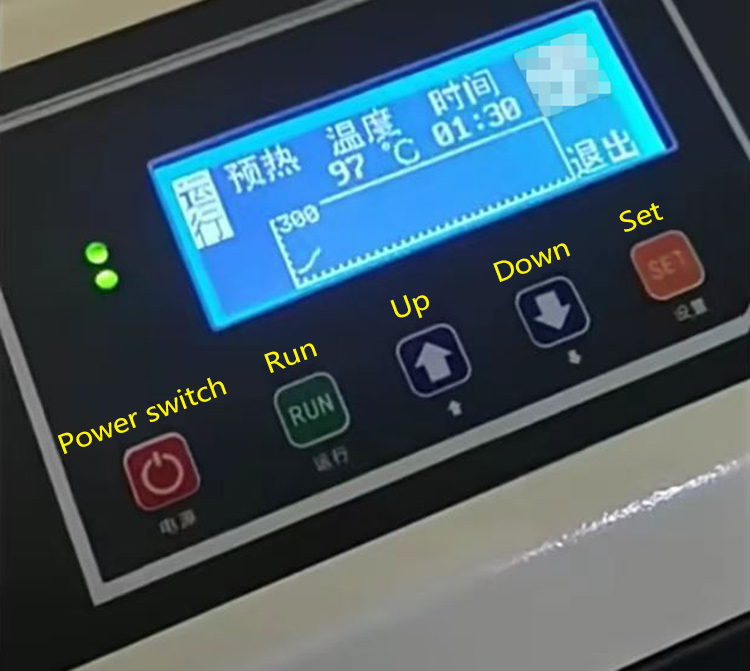
The operation panel of the equipment has five buttons: "Power switch," "Run," "Up," "Down," and "Set." The "Run" and "Set" buttons are multifunctional, the corresponding button functions will be displayed at the bottom of the screen in different operation interfaces.
IV. Setting operating parameters for the ZB5040HL lead free reflow oven
Before commencing the soldering process, it is essential to configure specific parameters for the reflow oven. When using the machine for the first time or when changing the tin paste formula, setting the operating parameters to meet usage requirements is typically necessary. Additionally, individuals can customize the machine settings based on their preferred language. The equipment offers two operating modes: "Reflow" and "Constant Temperature." The "Reflow" mode is designed for soldering SMT circuit board components, encompassing five temp stages: preheat, heating, soldering, heat preservation, and cooling. In contrast, the "Constant Temperature" mode is intended for disassembling circuit board components or drying items, featuring a single temp setting stage. Before initiating the heating process, please verify that the set temperature and duration values are reasonable.
1. Power on
Turn on the main power switch located at the back of the equipment. The topmost red indicator light on the left side of the screen will illuminate. Press the "Power" button on the panel. The LCD screen will display "Preset," "Production," and "Constant Temperature" options.
2. Language setting
Before pressing the "Power" button, ensure the equipment is powered on. Long press the "SET" button to enter the setup menu. Press the "Down" button to navigate to the language setting and toggle between Chinese and English.
3. Production mode setup
(1) After pressing the "Power" button, "Production" will be reverse white state, indicating it is selected. Press the "RUN" button to display the settings. Use the "SET" button to select "Preheat," "Temperature," and "Time." When "Preheat" is selected, press "SET" to switch to the "Temperature" field, which will be reverse white state. Use the "Up" and "Down" buttons to set the preheat temp, with a minimum of 70°C. Press "SET" again to switch "Time" to the reverse white state and set the keep time.
(2) Press "SET" to switch back to the "Preheat" field. Press "Down" to change to "Heating." Repeat the process of pressing "SET" to reverse white state "Temperature," then use "Up" and "Down" to adjust the temp, which should be higher than the preheat setting. Press "SET" once more to switch to "Time" and set the keep time.
(3) Press "SET" to select "Heating." Press "Down" to switch to "soldering." Again, press "SET" to reverse white state "Temperature" and adjust it using "Up" and "Down." Press "SET" to switch to "Time" and set the keep time.
(4) Press the "SET" button to switch to the "Soldering" field, which will be reverse white state. Press the "Down" button to change to "Heat preservation." Press "SET" again to switch to the "Temperature" field, which will be reverse white state. Use the "Up" and "Down" buttons to set the soaking temp, which should be lower than the soldering temperature. Press "SET" once more to switch to the "Time" field, which will now be reverse white state, allowing it to set the holding time.
(5) Press the "SET" button to switch to the "Soaking" field, which will be reverse white state. Press the "Down" button to change to "Cooling." Press "SET" again to switch to the "Temperature" field, reverse white state, and use the "Up" and "Down" buttons to set the temp. Note that the soaking temperature range should be lower than the soldering temp. In the Cooling mode, the "Time" cannot be set and defaults to 00:00.
4. Setting the constant temperature mode
After pressing the "Power" button, "Production" will be reverse white state. Press the "Down" button to select "Constant Temperature," which will become reverse white state, indicating it is selected. Press the "RUN" button to confirm and enter the mode. Use the "Up" and "Down" buttons to set the temp. Press "RUN" to start and "SET" to exit.
5. Setting the preset mode
(1) After pressing the "Power" button, "Production" will be reverse white state. Press the "Up" button to select "Preset," which will become reverse white state, indicating it is selected. Press the "RUN" button to confirm and enter. Use the "Up" and "Down" buttons to navigate between "Leaded Soldering 1," "Leaded soldering 2," "Leaded soldering 3," and "Lead Free soldering" for setting.
(2) After selecting "Leaded soldering 1," press "SET" to start setting. Use "SET" to switch between heating stages, temp, and time. Use "Up" and "Down" to adjust temperature and time. Press "RUN" to exit. Press "RUN" again to save the preset, which will automatically switch back to the main interface of "Preset," "Production," and "Constant Temperature." When entering the "Production" interface, the time and temp settings will be the preset values.
(3) The preset mode can store up to 4 sets of heating data: Leaded soldering 1 to 3 and lead free soldering. Users can preset different parameters for different substrates and solders to save time and avoid frequent parameter adjustments.
6. System parameter settings
Before pressing the "Power" button with the equipment powered on, long press the "SET" button to enter the system parameter settings. Press the "Down" button to switch and view all contents. The system parameters are preset at the factory and generally do not require adjustment unless under special circumstances. Adjustments should be made under the guidance of the manufacturer to avoid system malfunctions or heating issues.
System parameter introductions:
Language: The device supports both Chinese and English languages, which can be switched using the setting button.
Adjustment mode: Allows individual testing of functional modules to diagnose equipment condition.
Room temp compensation: Corrects temperature deviations caused by inaccurate room temp.
Temperature coefficient: Adjusts temperature accuracy under high temperature conditions.
PID P: Proportional term in the PID algorithm.
PID I: Integral term in the PID algorithm.
PID D: Derivative term in the PID algorithm.
Preheat, heating, soldering, and heat preservation each have maximum time limits, including the time from start to reaching the set temp plus the keep time. Exceeding these limits will trigger an alarm, initiate cooling, and stop the machine to prevent overheating of the PCB. Over temperature refers to any temp zone exceeding the set value plus an offset, triggering an alarm and shutdown to ensure PCB safety.
V. Soldering operation
After completing the parameter settings, the equipment is ready for proper and safe operation. We will open the drawer furnace of the reflow soldering machine, which is designed to heat the entire circuit board. Therefore, place the circuit board to be soldered smoothly in the center of the tray,leaving a 30mm gap on all sides, and then close the drawer of the furnace.
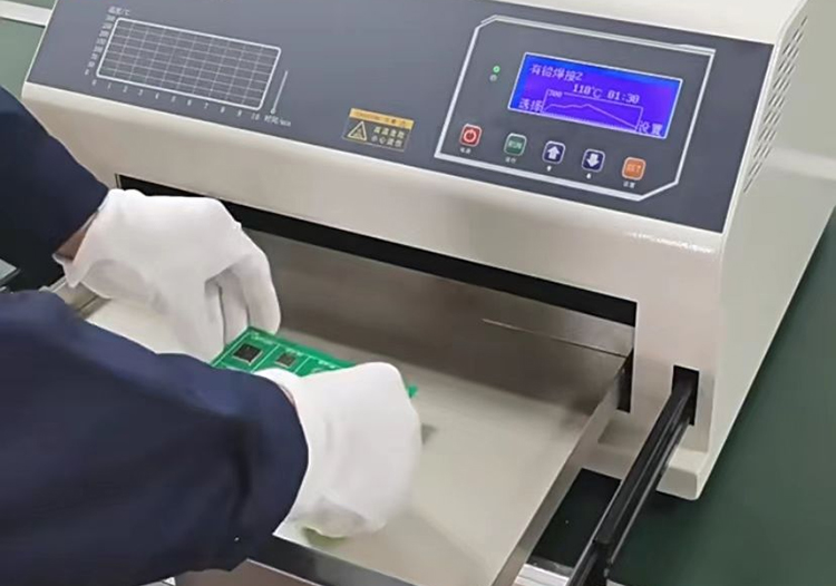
Once in the production mode, press the "RUN" button to initiate the working state. The display shows that the "Run" icon on the upper left is reverse white state, displaying the current temperature inside the chassis and the hold time value. When the temp reaches the set point, the countdown begins, and after completion, it proceeds to the next segment. As the equipment reaches the constant temperature stage in each temp segment, the indicator light on the lower operation panel will flash. If the actual temperature exceeds the set temp by approximately 5°C, the machine will activate the fan for brief cooling, and the power indicator light above the operation panel will flash. To exit the operation midway, press the "SET" button. When the equipment enters the cooling segment, the fan will operate at full capacity, with the power indicator light off. When the temp drops to the set temperature, the buzzer will alarm and the display will display "Complete" in reverse white. For safety, the cooling fan will continue to operate until the temp falls below 80°C, then it will stop.
VI. Connection to computer operation
The ZB drawer type reflow soldering machine is equipped with a DB9 pin interface for connecting to a user's computer, allowing users to operate the reflow soldering process and monitor the temp curve in real time through the computer.
1. Device connection
Connect one end of the provided serial port extension cable to the DB9 interface on the right rear side of the reflow soldering machine, and the other end to a computer equipped with a DB9 interface. Then, power on the reflow soldering machine and press the "Power" button to illuminate the screen. Navigate to the Device Manager on the computer, check the Ports section, and record the name of the communication port. Double click to open the reflow soldering monitoring software, select the recorded communication port name under "Port," click "Open," then "Connect." The reflow soldering display screen will show "Communicating with Host..." and the software information bar will indicate that the device is connected.
2. Parameter setting
Tick the "Temperature and Time" section in the reflow soldering mode to set the temp and time for each segment of the reflow soldering process. After setting, click "Run" to display the real time temperature in the "Current" column and the real time temp curve in the lower right corner. To enable the constant temperature mode, enter the desired constant temp in the set box under the "Current" column.
VII. Temperature setting reference
Tin paste type | Low temp tin paste | Medium temp tin paste | High temp tin paste |
Melting point | 138℃ | 183℃ | 217℃ |
Preheating section | 130℃ | 150℃ | 150℃ |
Keep time | 90s | 90s | 90s |
Heating section | 150℃ | 180℃ | 180℃ |
Keep time | 30s | 30s | 30s |
Soldering section | 185℃ | 230℃ | 225℃ |
Keep time | 2s | 2s | 2s |
Heat preservation section | 180℃ | 225℃ | 250℃ |
Keep time | 2s | 2s | 2s |
Cooling section | 100℃ | 100℃ | 100℃ |
Cooling time | 0s | 0s | 0s |
1. Temperature setting reference value
The table above provides reference temp settings for three commonly used tin pastes. Select the corresponding reference data based on the type of tin paste used, and make fine adjustments within the reference range according to the size of the PCB board and the distribution density of components. Larger boards with denser component distribution require higher temperatures and longer keep times, while smaller boards with lower component density should have correspondingly lower temp and shorter holding times.
2. Precautions for temperature settings
Adjust the temp and keep time gradually from low to high. Under the premise of ensuring soldering quality, try to reduce the temperature and keep time as much as possible to prevent discoloration of the PCB board and damage to components.
Set the temp of the soldering segment based on the melting point of the solder. Generally, the temperature value of the soldering segment is the melting point temp plus about 30 degrees, and try to shorten the duration of this high temperature stage to prevent the PCB board from burning.
If the PCB board does not melt the tin or only partially melts it, first try increasing the temp and keep time of the heating segment. If this is ineffective, consider adjusting the settings of the soldering segment.
VIII. Fault alarms
When the temperature measuring element is damaged, an automatic alarm will sound and display "Sensor Failure." If the furnace temp does not change, it will report "Heating Failure." If any heating time exceeds the maximum timeout protection time set by the system parameters, the display will show "Heating Timeout." If the temperature deviates from the set value and reaches the over temp standard, it will report "Heating Over Temperature."
IX. Daily maintenance and care
Regularly check if the drawer tray is clean, remove debris, and wipe off grease and dirt from the inner walls. Clean the observation window glass with an alcohol soaked cloth to ensure it is clear and not blurred. Inspect and clean the dust on the cooling fan blades on the left, right, and rear sides of the equipment. Use a clean cloth to wipe the exterior of the equipment, remove accumulated dust, and maintain the overall cleanliness of the equipment.
Dear Customers,
Hello, April 4, 5 and 6, 2025 (GMT+8) are the traditional Chinese festivals - Qingming Festival. Our company will suspend shipments during these 3 days and resume shipments on April 7 (GMT+8). We are deeply sorry for the inconvenience. Thank you for your understanding and support.
Best wishes,
ZEUS MINING CO., LTD