


Summary: This repair guide is mainly used to introduce the repair process of the Innosilicon A10 hash board. Organized, adapted and shared by ZEUS MINING.
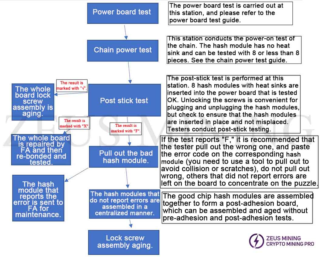
Please note: The power board can only be used for chain testing and post-stick testing after the power board test is OK. Since the bottom of the power board is not insulated, please test it on an insulating pad.
Power board test:
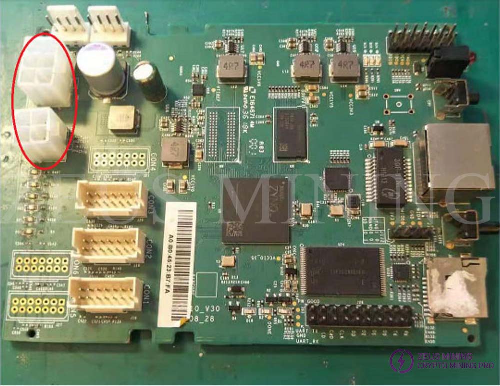
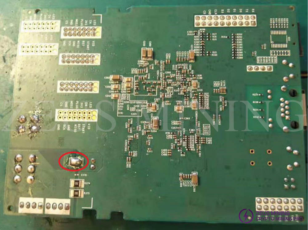
1. Prepare 1-2 Golden samples, as follows, short-circuit R307 (marked in red) with a 0Ω resistor, and attach the heat sink, because this sample will be tested for a long time, this sample is specially used as a power board test sample.
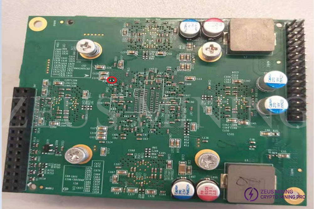
2. Before the test, please check whether the power board is connected to tin or the connector is poorly soldered, and then use a fixed output 12V power supply to insert a golden sample into the power board to be tested, as follows, and connect the power supply and the control board (Please refer to step 3 for the selection of the control board), use the power supply board test program to test. If it reports "√", that is, the power supply board test is OK; if it reports "X", please repair it.
3. Control board selection
Method 1: Use T1 control board, there is only one fan interface.
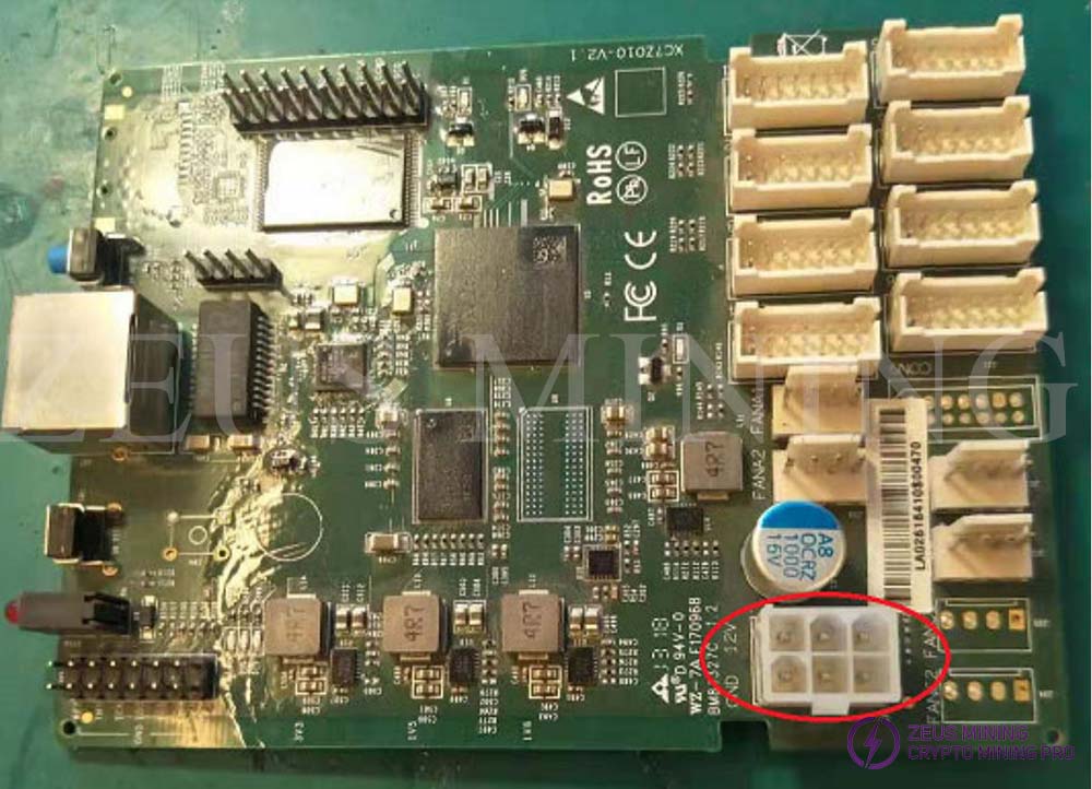
Method 2: Use T2T series control board, there are two fan interfaces, but R394 needs to be short-circuited.
Test for testing the chain:
The power board sample for the test chain test must be tested with a power board that has passed the power board test.
Method one:
Insert the 8 hash modules without heat sinks into the power board that has been tested OK. The power board does not need to perform any operations. Check whether each hash module is plugged in tightly. Use the chain test program to test. If it shows "√", means that the test is OK, install the heat sink, and then carry out the post-stick test. If the test result shows "X", means that there have fault and need repaired.
Method Two:
Plug in one or more hash modules for testing, but the power board needs to short-circuit the pin2 & pin4 of the power board socket that is not plugged into the hash module. For example: if the hash module to be tested is plugged into the 1st position of the power board, you need to short-circuit pin2 & pin4 of the 2nd position connector; If the hash module to be tested is plugged into the 1st position and 2nd position of the power board, you need to short the pin2 & pin4 of the 3rd position connector;
Test for post-stick
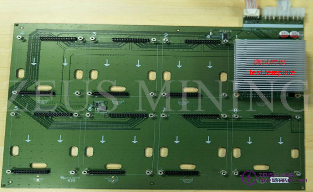
Test with the latest test program (version number v2.16.3) after sticking. The following picture is a general connection diagram for reference.
1 power supply is connected to 1 hash board and 1 control board for testing. The hash board needs to be placed on an insulating pad for testing, corresponding to one cooling fan; Or test it in a mining box (it is best to put 1 hash board in a mining box for testing). The fastest test time after sticking is about nine minutes, please try to test as many test racks as possible at the same time.
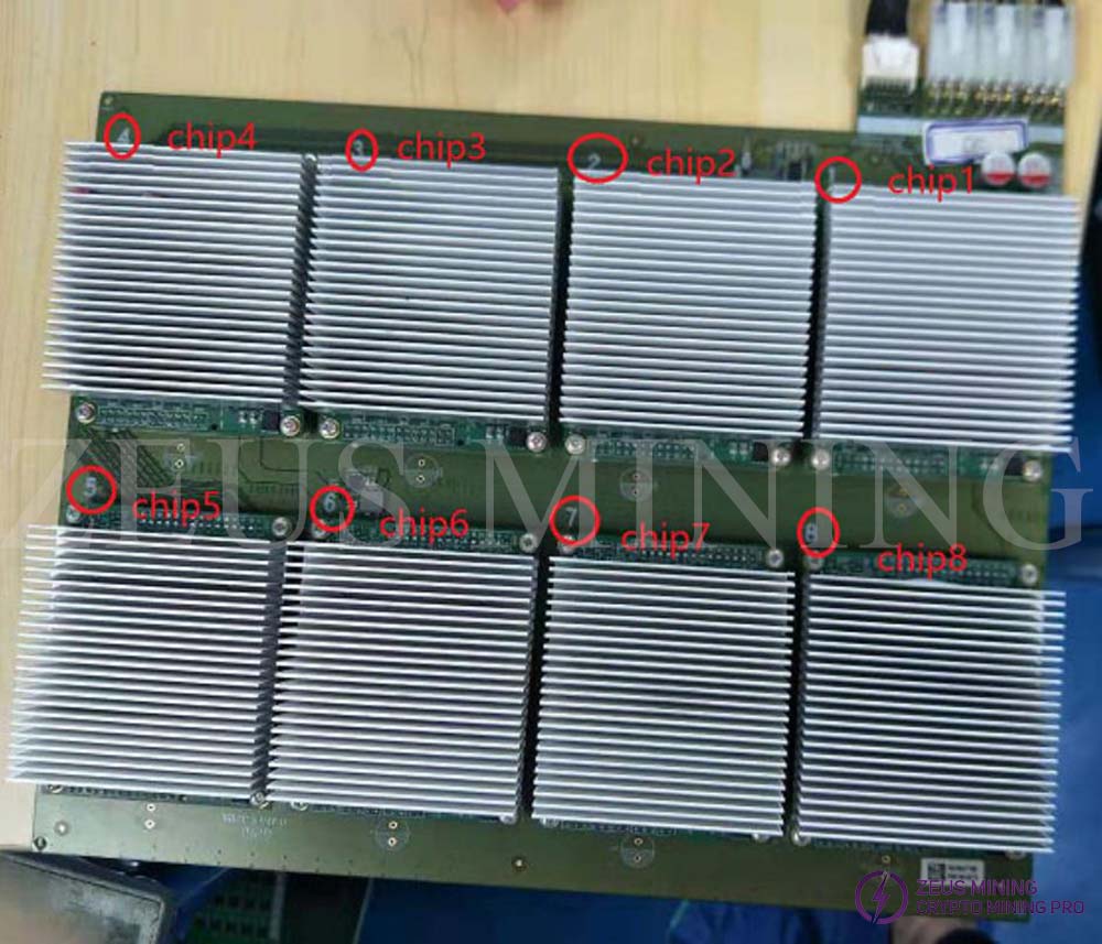
The numbers on the power board correspond to the chip tag numbers, as follows:
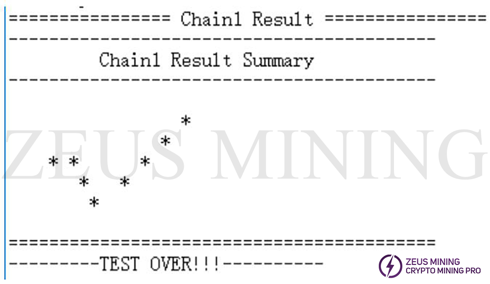
There are generally 3 types of test results for post-stick testing: "F", "X", and "√". Among them, the case where the display result is "F" is the most.
Processing method to display result "F":
When the test result interface displays "F", it means that some chips are OK, and the chip that reports an error needs to be re-tested.
1. Affix a removable art glue on the heat sink of the error-reporting chip, and write the corresponding error code. For example, the error is as follows:
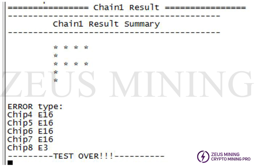
Chip 4, chip 5, chip 6, chip 7 and chip 8 need to be re-tested. Please paste the art glue on the corresponding chip and write the error code. The chip 1, chip 2 and chip 3 that did not report an error can be determined to be good .
2. Dismantling the hash module and reinstalling the hash module link
The test man removes the hash module affixed with the art glue from the post-sticking power board, and places the removed error-reporting hash modules in a centralized manner. If it is determined that the hash module is good, it will be left on the power board. Finally, it can be assembled with other hash modules that are also determined to be good, and the assembled ones can be directly assembled and aged.
3. FA analysis
In the centralized error reporting hash module, FA analysis and repair will be carried out on the ones with E3 / E15 / E16 / E19 error codes. E3 E15 and E16 can be reconstituted together to form a post-sticking board (8 pieces), the hash module can be used for post-stick retest analysis, and E19 does not need to be retested. Waiting for the results of the analysis.
Processing method to display result “X”:
If the test result interface displays "X", the entire board needs to be analyzed:
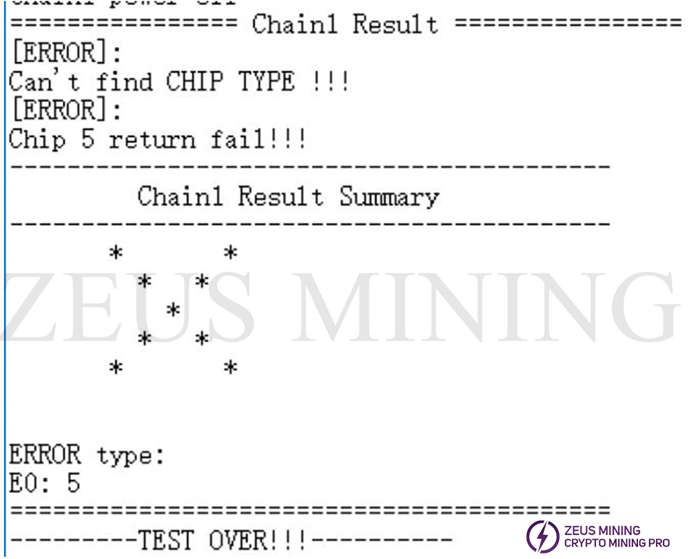
E0: X---chain failure
If the eight hash module test chain reports E0:X, it is generally because the X-th chip has a problem. You can remove this chip and replace it with a good hash board for verification.
If it is determined that there is a problem with this hash board, you can use the repair program to test this board separately for the following analysis:
① Measure voltage: Use a small power board to measure whether the Vcore (about 0.8V) powering the A10 chip is normal, whether VDDQ (1.35V) and three LDO voltages (two 1.8V, one 0.8V) are normal. If 0.8V and 1.35V are abnormal, you can first measure whether the EN pin is 3.3V, and then analyze whether the DCDC module is abnormal; if there is no output of 1.8V and 0.8V of LDO, it is LDO abnormal;
② Measure the clock signal: whether the 5 channels driven by the two crystal oscillators are all 50M;
③ Measure control signal: whether Reset / Start are both 1.8V;
④ Measure the SPI signal: The oscilloscope measures whether there is sck_I, cs_I, sdi_I and sdo_I at the input of the socket; measure the sck_O, cs_O, sdi_O and sdo_O output to see if it is abnormal. If it is abnormal, then measure whether the 47Ω resistor connected to the SPI signal behind the socket is abnormal.
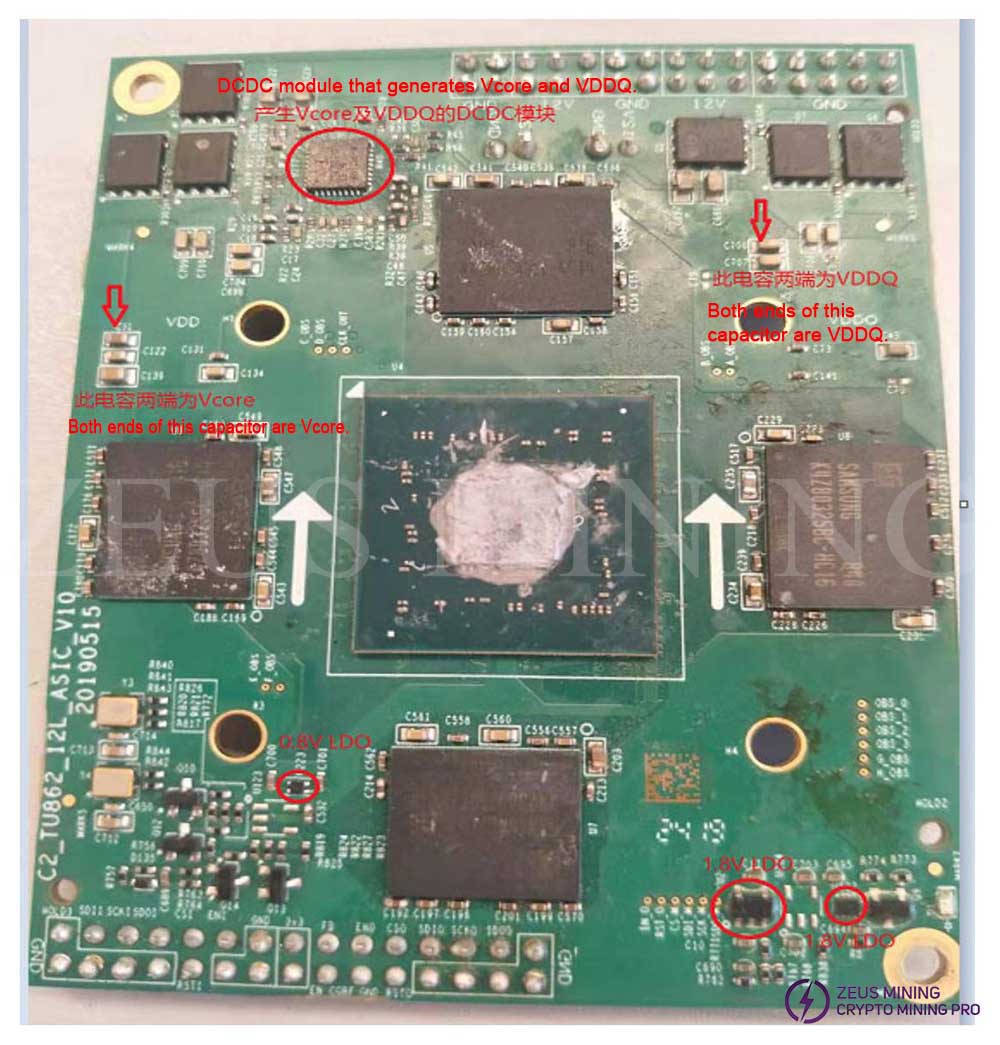
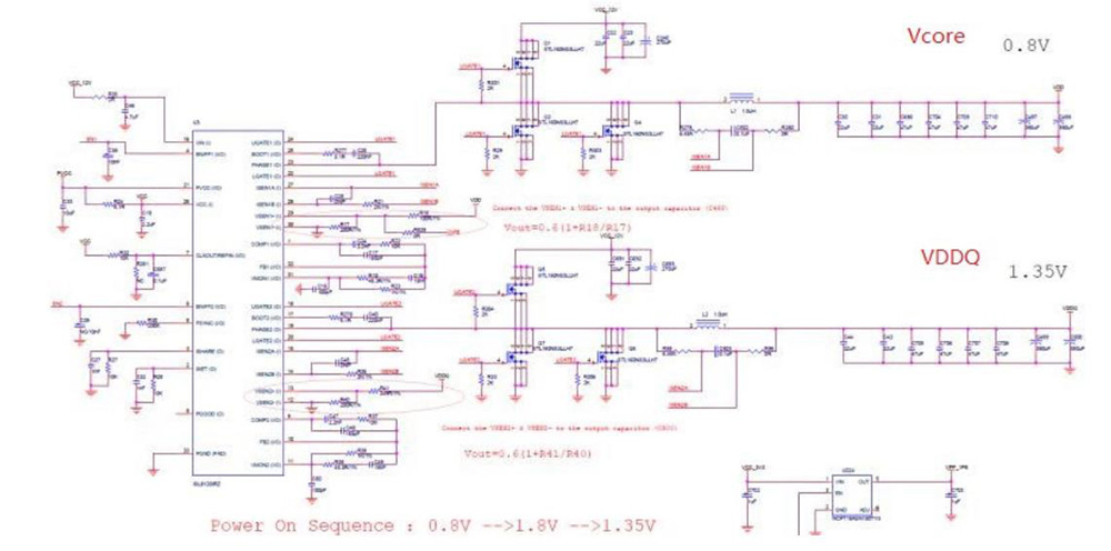
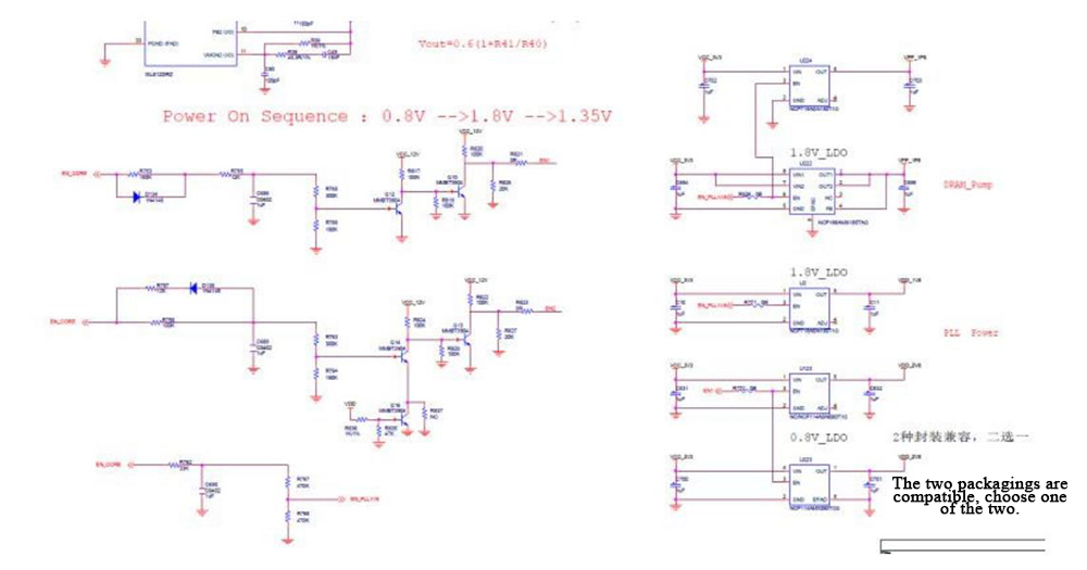

E3: X---chip job all wrong
The board can be tested separately with the post-sticking program for the following analysis:
① Measure Vcore voltage and ripple, the voltage needs to be 0.8~0.85V, and the ripple is within 35mv;
② Use the 4G post-sticking program to see if it still reports E3, and go to step 3 if it still reports E3;
③ Contact us for analysis assistance.
E4: X---PLL unlock
If it is determined that there is a problem with this Hash module, you can use the repair program to test this board separately for the following analysis:
① Measure the clock signal: whether the 5 channels driven by the two crystal oscillators are all 50M;
② Measure whether the Vcore, and the VDDQ voltage supplied to the four particles are normal;
③ Contact us for analysis assistance.
E14: X---core bist error
If it is determined that there is a problem with this hash module, you can use the repair program to test this board separately for the following analysis:
① Check the log, observe whether the number of Sub_good_core is more than 390, and measure whether the Start signal is 1.8V;
② Measure the clock signal: whether the 5 channels driven by the two crystal oscillators are all 50M;
③ Measure whether the Vcore, and the VDDQ voltage supplied to the four particles are normal;
④ Contact us for analysis assistance.
E15: X--- write dag wrong
① Measure the clock signal: whether the 5 channels driven by the two crystal oscillators are all 50M;
② Measure whether the Vcore, and the VDDQ voltage supplied to the four particles are normal;
③ Contact us for analysis assistance.
E16: X---DDR training error
The board can be tested separately with the post-sticking program for the following analysis:
① Check the log to see if it is a 4G training error or a training error after overclocking. If it is a 4G training error, go to step 2. If there is a training error after overclocking, you need to run three or four times to check the stability. If sometimes OK and sometimes not OK, and the stability is high, it can be used as a normal board, if it is not OK all the time, it can be used as a maintenance board;
② Check which side of the log failed the training, and then measure the power supply VDDQ and clock signal on that side. If it is normal, you need to change the particle on that side for verification;
③ Contact us for analysis assistance.
E17: X---Dag preparation error
The board can be tested separately with the post-sticking program for the following analysis:
① Check the log, observe whether the number of Sub_good_core is more than 390, and measure whether the Start signal is 1.8V;
② Measure whether the Vcore, and the VDDQ voltage supplied to the four particles are normal;
③ Contact us for analysis assistance.
Processing method to display result “√”:
If the test result interface shows "√", you can directly lock the screws, and then assemble and aging.
Innosilicon A10 common error codes and their corresponding processing methods:
| Test session | Test Results | Error code | Error code description | Reasons | Approach |
| Power board test | X | E0:1 | Chain failure | 1. It is used for the power board test sample is bad, broken or not looped back; 2. The power board under test is defective, and there is no output at 12V or 3.3V. | Repair |
| E18 | Power board cannot be regulated (new) | Programming failed | Reprogram or replace the DAC chip | ||
| √ | None | Good product | |||
| Test before sticking | X | E0:1 | Chain failure | 1. Test fixture problem: poor contact or bad power board sample 2. The tested hash module is failed | Repair |
| √ | None | Good product | |||
| Test after sticking | X | E0/E1~E13 | Same error code as BTC | FA analysis required | The whole board (including 8 hash modules) is sent to FA for repair. After the repair, the whole board is sent to the production line for re-testing the post-sticking. |
| E14 | core bist failure (new) | 1. The control signal Start-EN is not pulled high 2. Poor chip | |||
| E18 | Power board cannot be regulated (new) | Programming failed | |||
| F | E3 | Single chip error rate 100% | Processing methods are given after analysis | Paste the error code corresponding to the error-reporting hash module, unplug the error-reporting hash module, and send it to FA for analysis. The hash module that does not report an error is directly assembled and aged (no need to test before and after sticking) | |
| E15 | 3G chace writes wrong | ||||
| E16 | 10G ddr training failed | ||||
| E17 | dag generation failed | ||||
| E19 | 3G ddr training failed | ||||
| √ | None |