


Avalon A11 A12 Series Hash Board Repair Guide
Ⅰ. Avalon A11 A12 hash board introduction
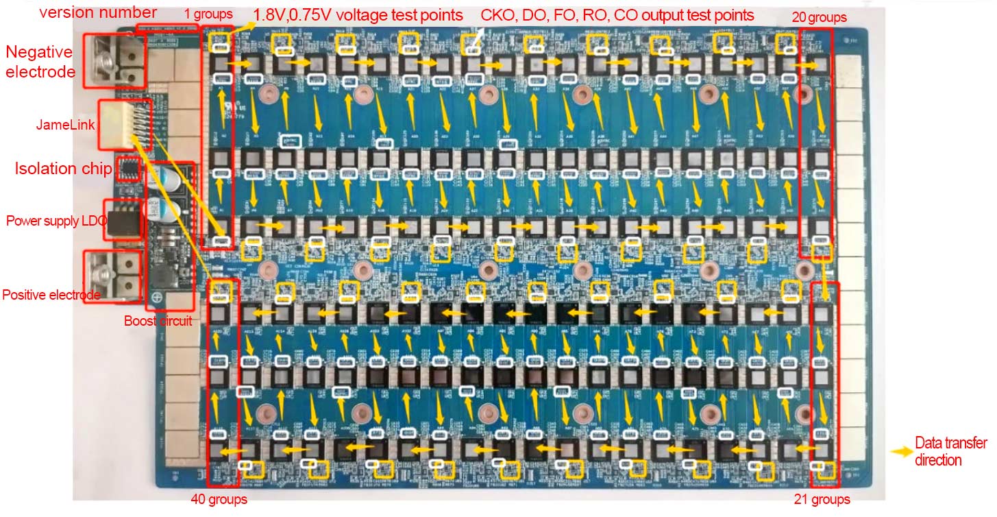
Figure 1: Hash board
HASH—S-A3201-X4030-V1-2-200929 version
A single hash board is connected in series by 120 A3201/3200 main chip signals, and each group is one domain. The overall layout is divided into 40 groups, and the groups are connected in series. The first 34 groups are powered by cross-domain 7, and the three main chips in each group are powered in parallel. Each group of voltages is: Vcore, VTOP, VDDIO. The signals are: CKin, Cin, Rin, Din and CKout, Cout, Rout, Dout. Each group has 2 LDO power, 1.8V—DDIO and 0.75V—TOP. 1.8V takes the power supply of the corresponding domain, and 0.75V takes the corresponding 1.8V power supply. There are voltage test points for Vcore, VDDIO, and VTOP on each chip side. The last 6 groups are separately powered by the boost circuit (17.7V), and then the U98 LDO is converted (13.9V~15V) to supply power to each group of LDOs.
Hash Board Interface
1. Power terminal: positive (+) negative (-) power supply
2. Jamelink interface data signal communication
HASH—S-A3201-X4030-V1-3-201116 version
1. V1-3-201116 version 1.8VLDO uses substitute materials for some materials. The locations on the materials are as follows:
2. Note: The position of the yellow mark in the picture is the position of the alternative material welded in the hash board in the opposite direction.
3. Before changing to 1.8VLDO, confirm the model package first.

Figure 2: Position of reverse welding of LDO substitute material
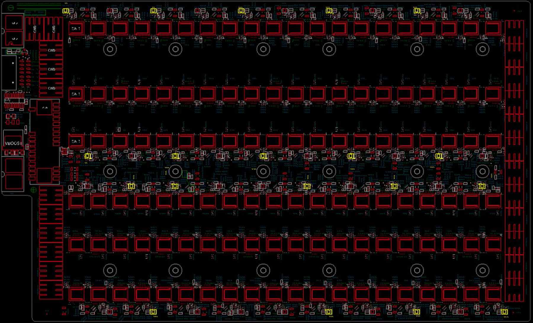
Figure 3: Location of LDO replacement material on the board
Ⅱ. Introduction to Test Fixtures for Repairing Hash Boards
Preparation tools: AvalonMiner 1066Pro 1166 1166Pro 1246 1246Pro Test Fixture
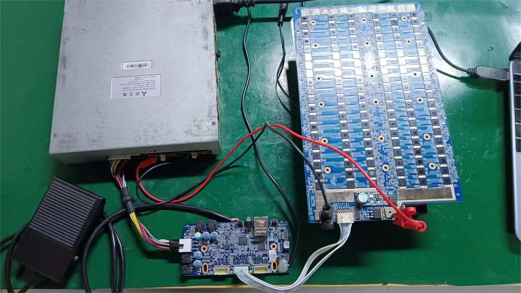
Figure 4: Test fixture connection diagram
Test fixture accessories:
Avalon Control Board 1066pro 1166pro 1246 1126 1248 *1
Innosilicon Avalon 7*2 14P data cable 30cm *1
Serial port tool:
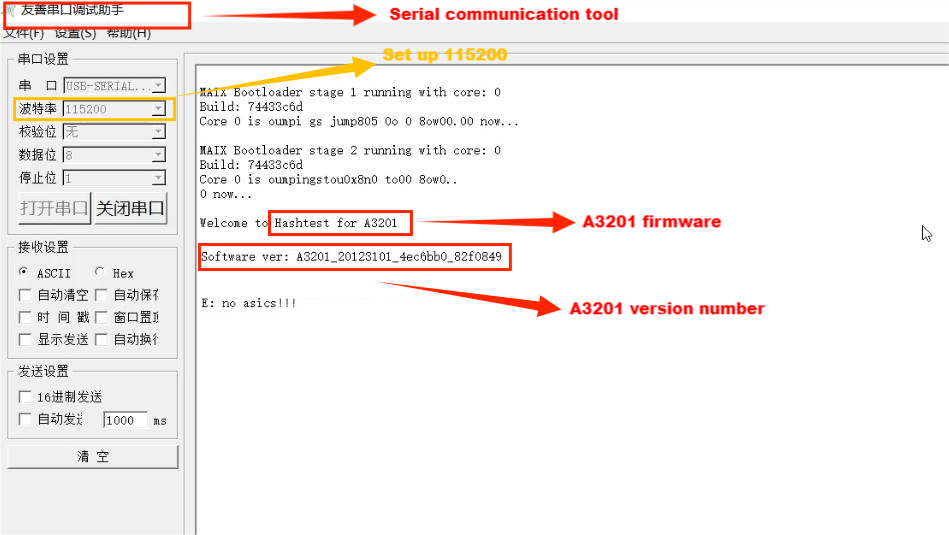
Figure 5: Serial port tool interface
Ⅲ. Chip pin definition
The following resistance parameters are for reference only 3201-BIN9.
Pin | Define | Resistance | Resistance | Define | Pin | |
1 | SEL | 191.3KΩ | 0.4Ω | VDD | 30 | |
2 | DSEL | 245.3KΩ | 0.4Ω | VSS_4 | 29 | |
3 | VDDTOP_1 | 0.433KΩ | 1.973KΩ | VDDPWL | 28 | |
4 | VDDPLL_FT | 1.454KΩ | null | FSOURCE | 27 | |
5 | VDDIOB_1 | 193.7KΩ | 0.444KΩ | VDDTOP_2 | 26 | |
6 | CKI_CO | 273.5KΩ | 0.2Ω | VSS_3 | 25 | |
7 | DI_RO | 238.5KΩ | 1.454KΩ | VDDPLL | 24 | |
8 | FBDO_FBDI | 365.6KΩ | 210.8KΩ | VDDIOB_FT | 23 | |
9 | RI_DO | 236.6KΩ | 332.7KΩ | VDDPVT | 22 | |
10 | CI_CKO | 220KΩ | 2.124MΩ | VDDIOA_1 | 21 | |
11 | TO | 234.3KΩ | 2.385MΩ | CKO_CI | 20 | |
12 | VDDIOB_2 | 194.8KΩ | 2.383MΩ | DO_RI | 19 | |
13 | VSS_1 | 0.2Ω | 2.380MΩ | FBDI_FBDO | 18 | |
14 | VSS_2 | 0.2Ω | 2.380MΩ | RO_DI | 17 | |
15 | VDDIOA_2 | 2.121MΩ | 2.380MΩ | CO_CKI | 16 |
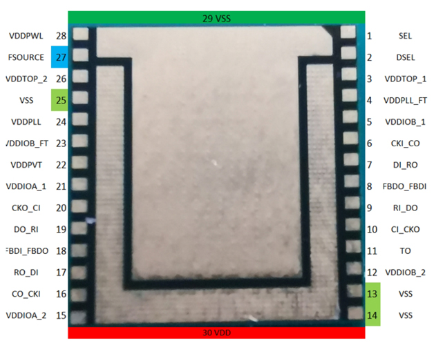
For A3203 & 01 products
After the SMT factory removes the chip that failed the functional test, please use a multimeter to measure whether there is a short circuit/open circuit between all pins of the chip and pin 29 (VSS).
The image above shows the number of each pin.
It is normal for pins 13, 14, 25 and 29 (VSS) to be short-circuited.
It is normal for pin27 and pin29 (VSS) to be open circuit.
If there is a short circuit or open circuit on other pins and pin29 (VSS), it will be judged as an abnormal chip. No cross-verification is required and returned directly by RMA.
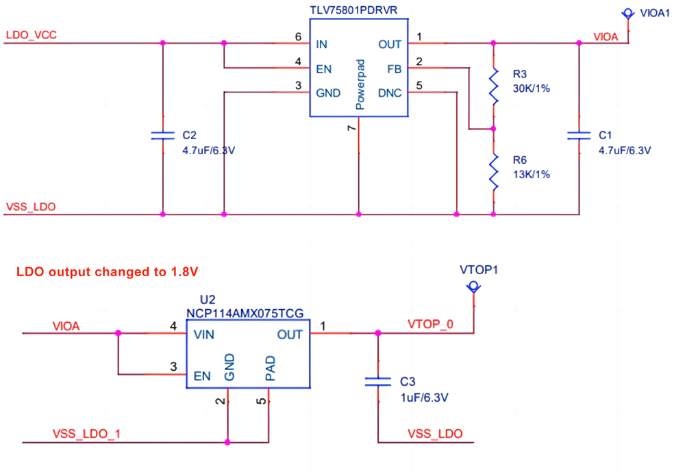
Figure 6: 1.8V and 0.75V LDO schematic
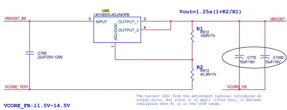
Figure 7: U98 LDO schematic
Ⅳ. Hash Board Repair Procedure
1. Keep complete machine maintenance records for subsequent retrospective analysis.
2. Make a note of the hash board with the heat sink that was removed from the complete machine. There is an SN QR code number behind the hash board that can be scanned via WeChat.
3. Preparation before repair: computer, oscilloscope, multimeter, magnifying glass, test fixture, heat sink, cleaning agent, tweezers, constant temperature heating station, heat gun, soldering iron, solder wire, flux, cotton swabs, dust-free cloth, temperature measuring instrument, electric screwdriver, silicone grease, steel mesh.
4. Read the hash board LOG information through the serial port to locate the hash board problem.
The number of asic count is 120 chips. If it is less than 120 chips, it needs to be repaired.
error 0 means no error value is reported.
volt represents the voltage value.
nonce: 0xc2b21b5 represents the working value of a single chip. If "nonce": is 0x0, maintenance is required.
copper 1 means there is a problem with the soldering at the bottom of the negative copper pillar and needs repair.
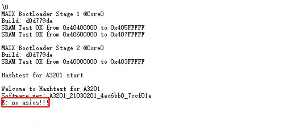
If "E: no asics!!!" appears when testing the hash board, it means there is a problem with the hash board, and the circuit is blocked and needs repair.
If the circuit is blocked, we need to measure each group of signals in sequence, including the four signals CK, D, R, and C:
CK: The working clock of the chip, the frequency is 4MHz;
D: The chip’s transmission data signal;
R: Reset pin of the chip;
C: The transmission clock signal of the chip, the frequency is 6.097MHz;
The oscilloscope is set to:
AC AC gear;
Amplitude is 1.00V/div;
Frequency is 200ns/div.
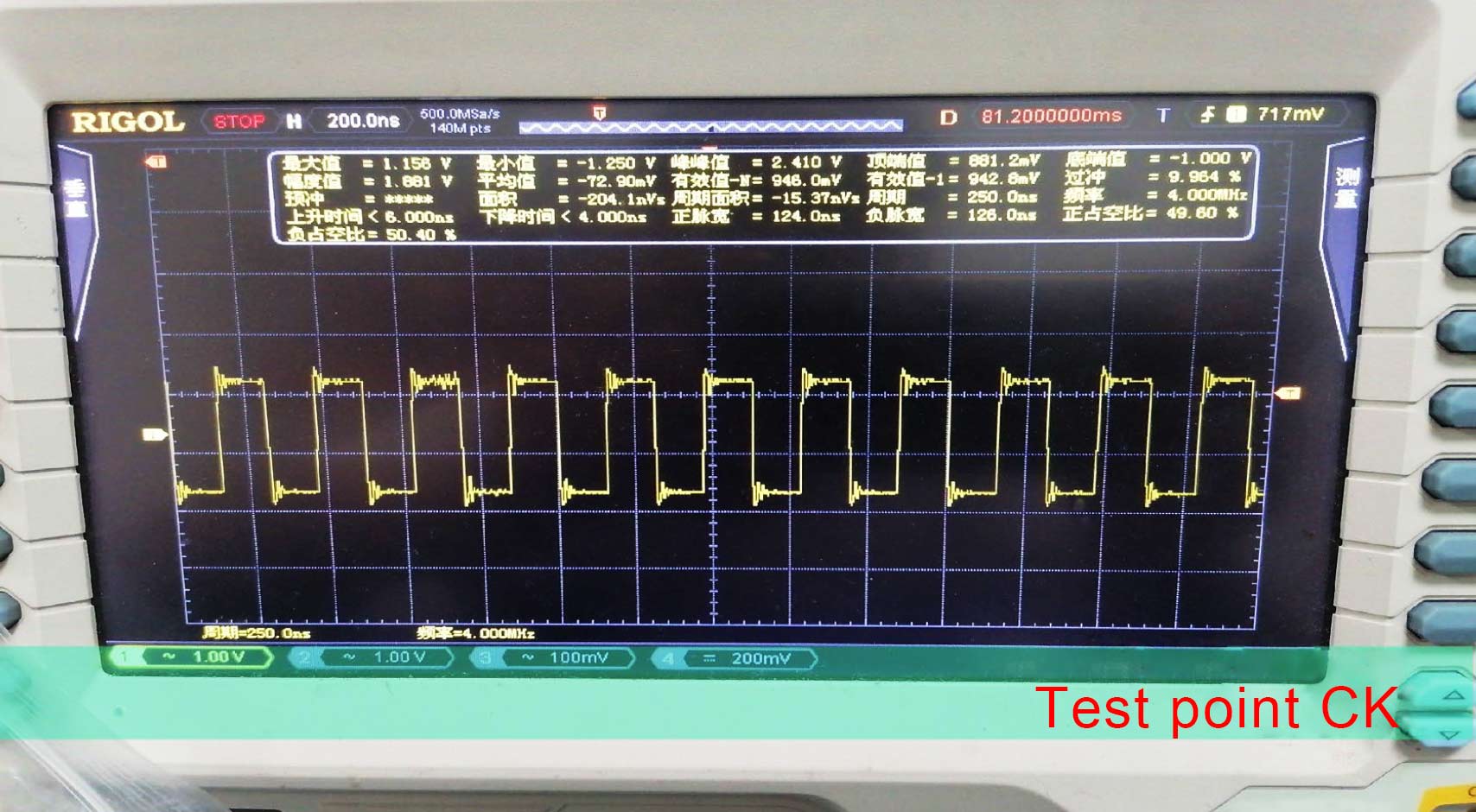
Figure 8: CK waveform, frequency 4MHz
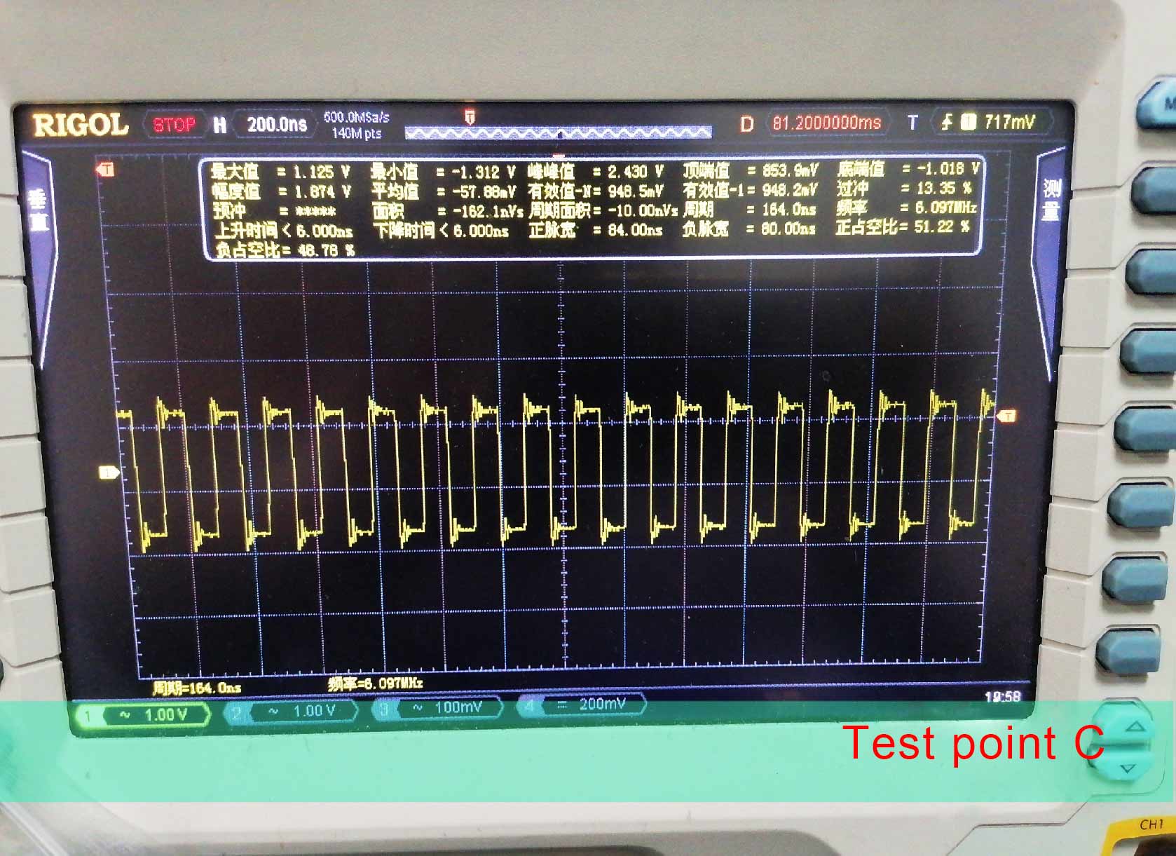
Figure 9: C waveform, frequency 6.097MHz
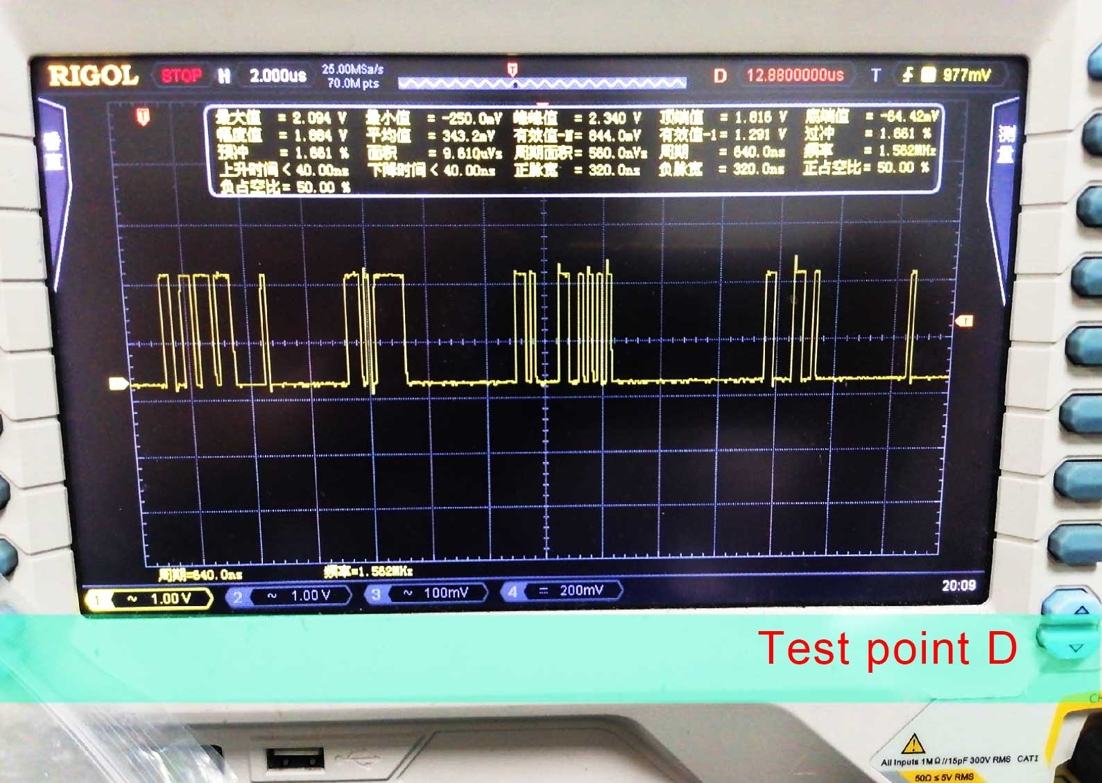
Figure 10: D waveform
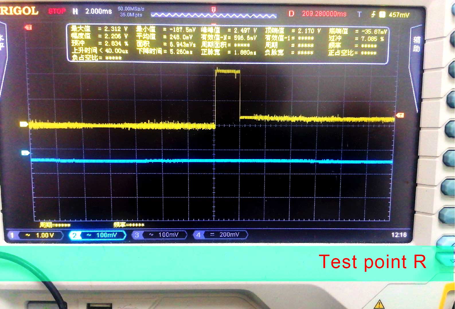
Figure 11: R waveform
Ⅴ. Soldering operation
1. Adjust the welding heating station to 235℃-240℃;
2. Adjust the soldering iron temperature to 280℃-380℃;
3. Adjust the heat gun temperature to 380℃-390℃ and wind speed 80-90;
4. Prepare the same BIN chip for replacement;
5. Before replacing the chip, the location of the replacement chip needs to be cleaned. After removing the chip, it is necessary to clean the foreign matter on the pad before applying tin. The pins of the pad must be fully tinned (add a little tin to the large pads at Pin29 and Pin30 to prevent continuous soldering), add a sufficient amount of tin to 1-28Pin at the bottom of the new chip (a small amount of tin is added to the large pads at Pins 29 and 30).
6. Chip Pin 1 should correspond to the pin 1 number of the hash board chip's pad, and the pads should be aligned left and right for welding (a small amount of soldering paste on the surface of the pad can help solder and position the chip).
7. Clean and inspect the solder joints of the soldered chip (the 28pin solder joints are full, there is no short-circuit phenomenon, and no tin beads overflowing)
8. Due to excessive temperature when repairing the hash board, surrounding components may loosen, and components may shift from the soldering pad or fall off due to misoperation such as unstable hands. It is necessary to check that the surrounding components are normal before powering on for testing.
Ⅵ. Troubleshooting Case Analysis
1. The log shows "asic count": 119, which means that not all chips have been found. We need to find the highest group from the "volt" information and then replace it. As shown in the picture below: the A19 A20 A21 chips corresponding to the 7th group need to be replaced.

Figure 12: Missing chip failure when reading
2. Unable to read BIN information. If the efuse value can be read, but the BIN information reads 0, the firmware needs to be upgraded.

Figure 13: BIN information cannot be read
3. BIN information error reported. An error occurs when reading the BIN information of the A31 ASIC chip, and a chip with the same BIN needs to be replaced.

Figure 14: BIN information error fault
4. The test result is E: no asics!!!, indicating that the hash board's chains are unavailable and the test failed.
(1) Check whether the Jamelink interface cable is plugged in properly, whether the interface is loose, and measure whether the voltage of the positive and negative terminals is normal.
(2) Use an oscilloscope to measure the C, R, F, D, CK test points of each set of chips, clean the chip with abnormal waveform, and check whether the solder joints of each pin are free of soldering; use the diode setting of the multimeter to measure the test point, specific parameters can refer to the data of the chips on the left and right sides; use the voltage gear of the multimeter to measure whether the voltage of a single group is normal 1.8V and 0.75V.
5. Locating chip method for multiple error information.
(1) Check whether the Jamelink interface cable (10-pin, defined CI pin) of the hash board is disconnected;
(2) Measure the CK signal test points of each group chips, and use the diode setting of the multimeter to measure chips with abnormal signals;
(3) Clean the pins of the abnormal chip and check whether there are any missing or poor soldering.
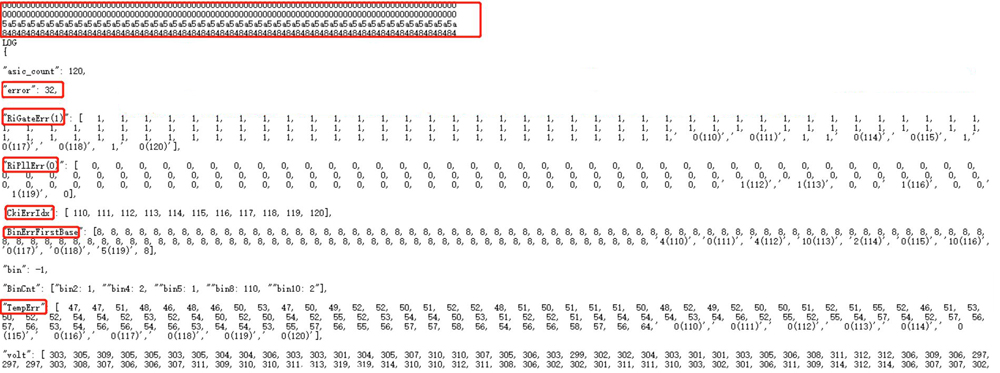
6. A21 error, check the soldering pins or replace it.

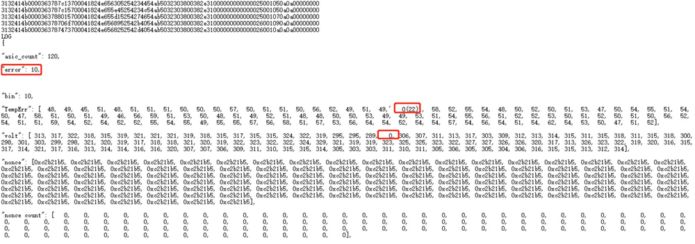
7. The test results show multiple error messages. First, we need to check whether the 4MHZ crystal oscillator is working correctly, and the material location is Y1; second, we need to check for soldering and chip problems, and the material locations are A1, A2, and A3.
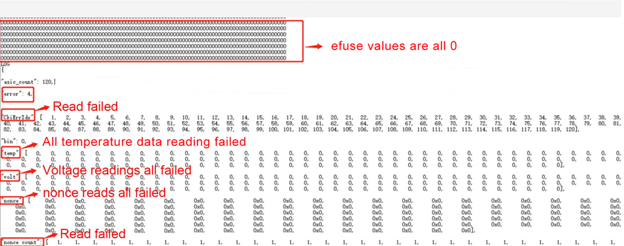
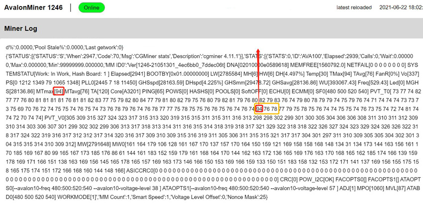
8. In case of abnormal temperature failure, the corresponding chip must be replaced. The temperature error between the left and right chips must not exceed 10℃. Remove the heat sink and check whether there is any abnormality in the thermal grease on the upper and lower sides of the chip (for example, there is less silicone grease, or the silicone grease is mixed with foreign matter). After replacing the chip, we need to test it on the machine and observe it for half an hour. It can be used normally only after the temperature becomes normal.
Dear Customers,
Hello, April 4, 5 and 6, 2025 (GMT+8) are the traditional Chinese festivals - Qingming Festival. Our company will suspend shipments during these 3 days and resume shipments on April 7 (GMT+8). We are deeply sorry for the inconvenience. Thank you for your understanding and support.
Best wishes,
ZEUS MINING CO., LTD