


Whatsminer Hydro-cooling Server Repair Guide
1. Repair environment construction, tools and equipment requirements
1.1 Test program: Mobxterm
1.2 Test commands:
Hash board testing: ft-readchipid
Power on: echo 1 > /sys/class/gpio/gpio356/value
When connecting test cables to control board ports 0 and 1:
- RST set to 1.8V: echo 1 > /sys/class/gpio/gpio197/value
- RST set to 0V: echo 0 > /sys/class/gpio/gpio197/value
When connecting test cables to control board ports 2 and 3:
- RST set to 1.8V: echo 1 > /sys/class/gpio/gpio202/value
- RST set to 0V: echo 0 > /sys/class/gpio/gpio202/value
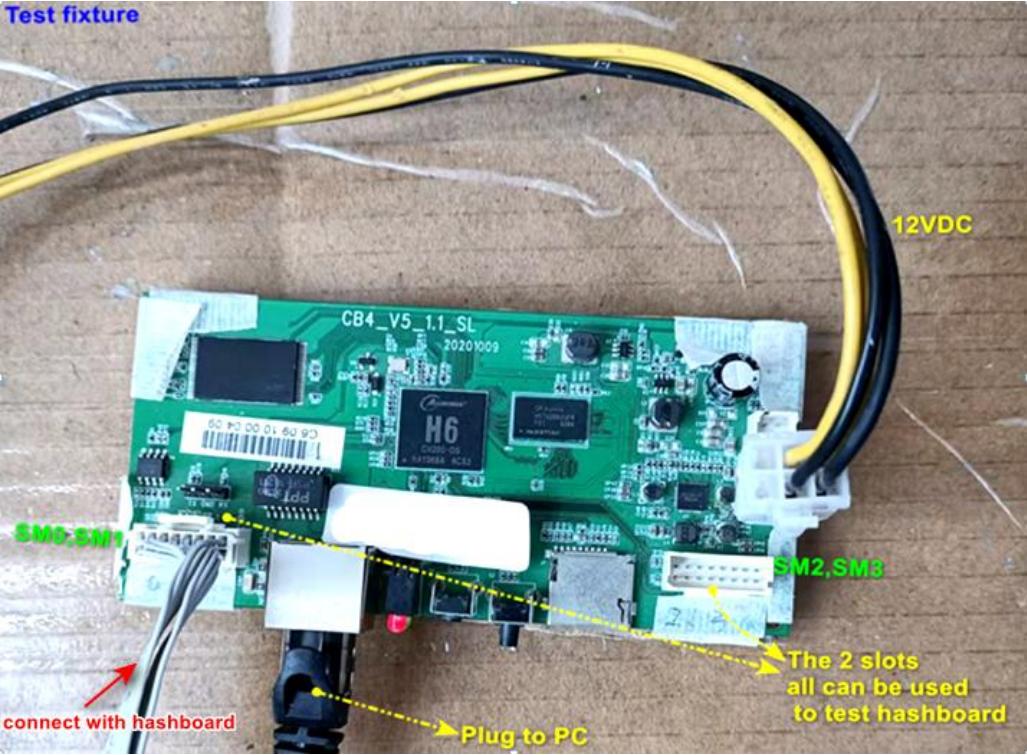
1.3 Control board of the test fixture: Hydro-cooled server control board (CB4/CB5/CB6)
1.4 Test cable: Communication signal cable that comes with the hydro-cooled server
1.5 Test fixture control board connection diagram:
1.6 Power supply required for testing:
Powering the hash board: 42V DC, 15A
Powering the tester control board: 12V DC, 2A
1.7 Tools and accessories:
Heating station, multimeter, oscilloscope, tweezers, solder paste, flux
2. Circuit principle introduction
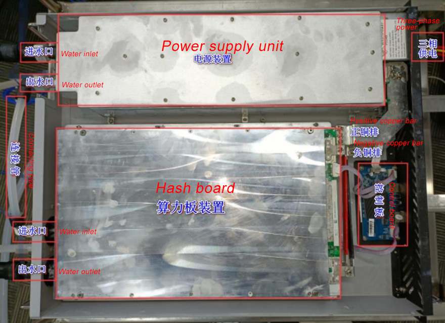
2.1 Overall machine structure
The miner consists of a three-phase power supply, a hash board, and a control board. The PSU and hash board are equipped with water-cooling heat sinks (as shown in the diagram)
2.2 Hydro hash board circuit description
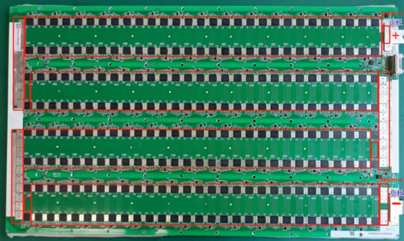
2.2.1 The circuit board series power is shown in the figure:
2.2.2 Signal loop:
A hash board consists of SM0 and SM1. SM0 signals RST, RXD, and CLK are transmitted from U1 to U116, TXD is transmitted from U116 back to U1 and returned to the control board via UP3.
SM1 signals RST (from SM0 U116), RXD (control board fed in from UP2), and CLK are transmitted from U117 to U232, TXD returns from U232 to U117 and is sent back to the control board via UP2.
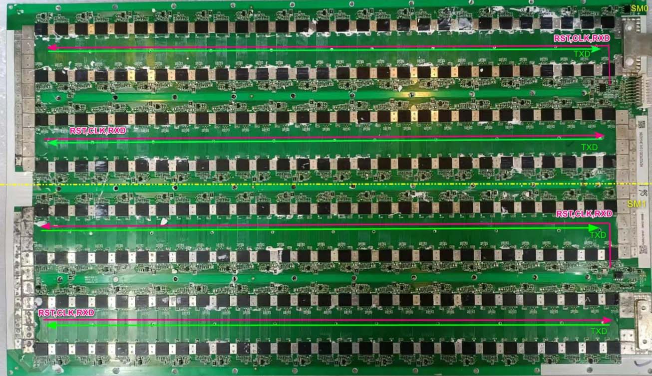
2.2.3 Each signal flow direction diagram of SM0 port
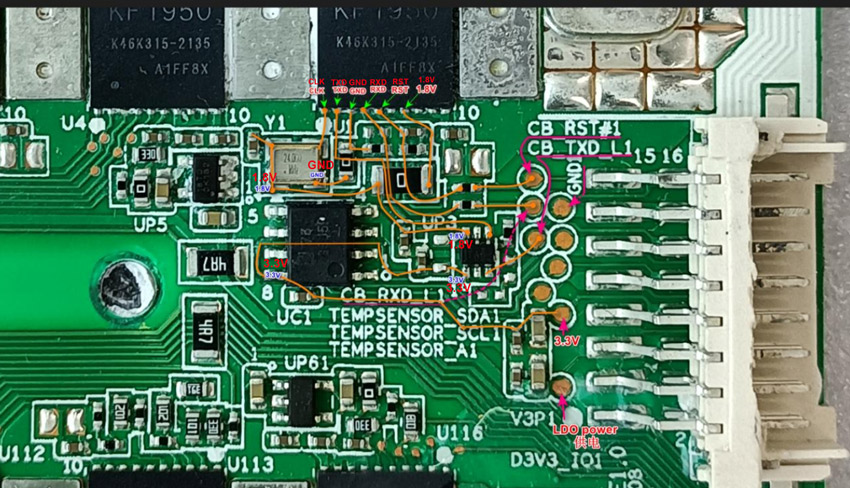
The control board powers the first 8 LDO chips of SM0. The initial state is low voltage with no input. Only when executing the POWER ON instruction or performing the hash board test does the voltage become high, and the 8 LDO chips obtain the input voltage.
2.2.4 SM1 port signal flow direction diagram
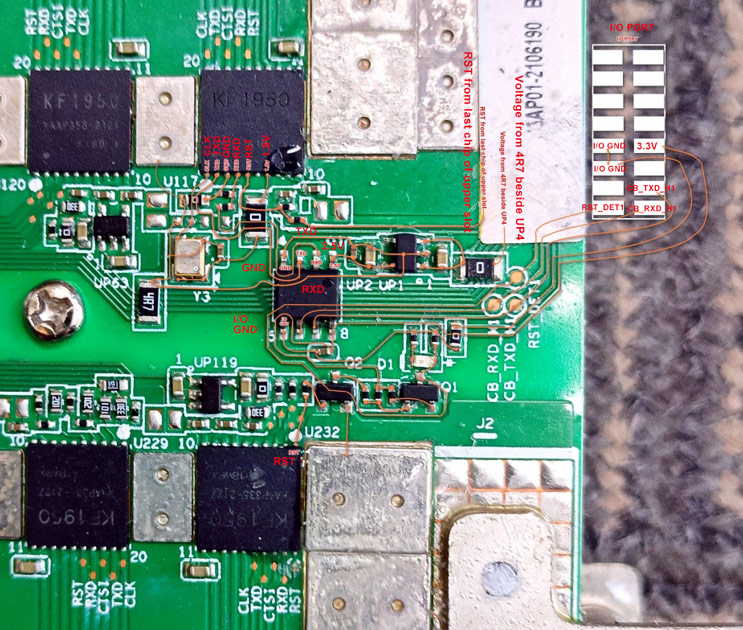
SM1's RST comes from the last chip U117 of SM0. The signals RXD and TXD need to be converted into levels by the UP2 chip, which enters and exits the control board through the I/O port. Only the RST signal runs through the entire board.
3. Safety precautions:
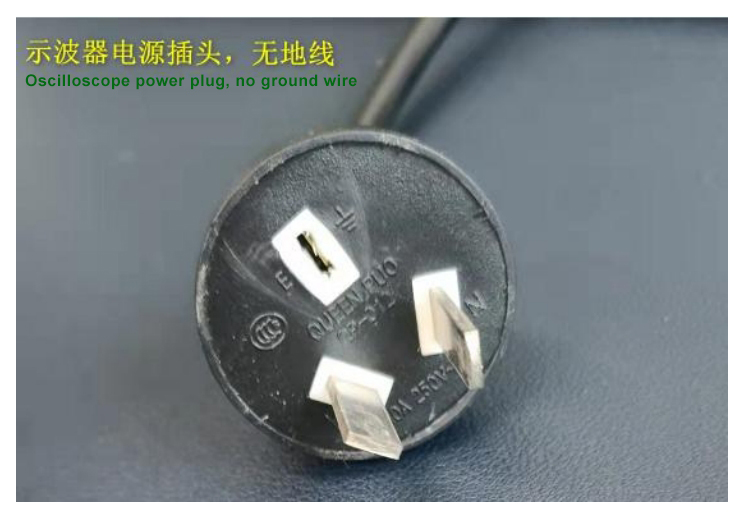
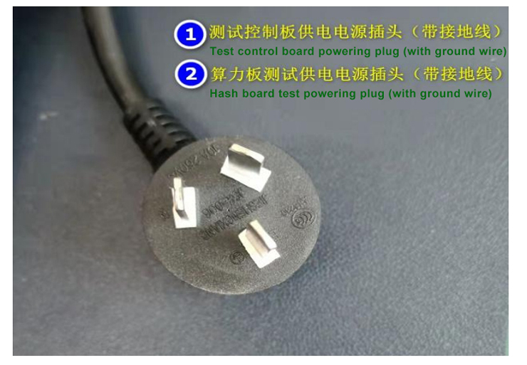
Since the power supply is three-phase AC input, to ensure personal safety, the power supplies for the test fixture control board and hash board must use 3-wire plug (including a ground wire) for reliable grounding. If using an oscilloscope to measure signals, the oscilloscope's power cord must have a 2-wire plug (without a ground wire); otherwise, there is a risk of electric shock as the hash board may carry 110V AC.
4. Soldering requirements:
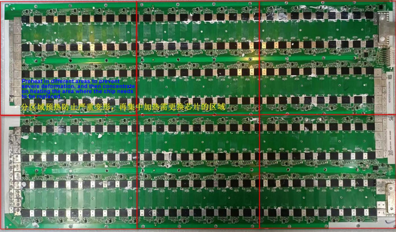
When soldering chips, the entire board must be preheated evenly before heating the area where the chip needs to be replaced. If preheating is not carried out in advance, due to the large area of the hash board, it will deform, causing the chips in other areas to desolder. In severe cases, the pads may even separate from the substrate, leading to scrapping.
5. Assembly precautions
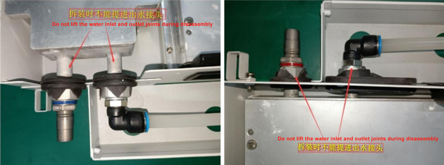
5.1 When disassembling, do not lift the heat sink water inlet and outlet joints by hand.
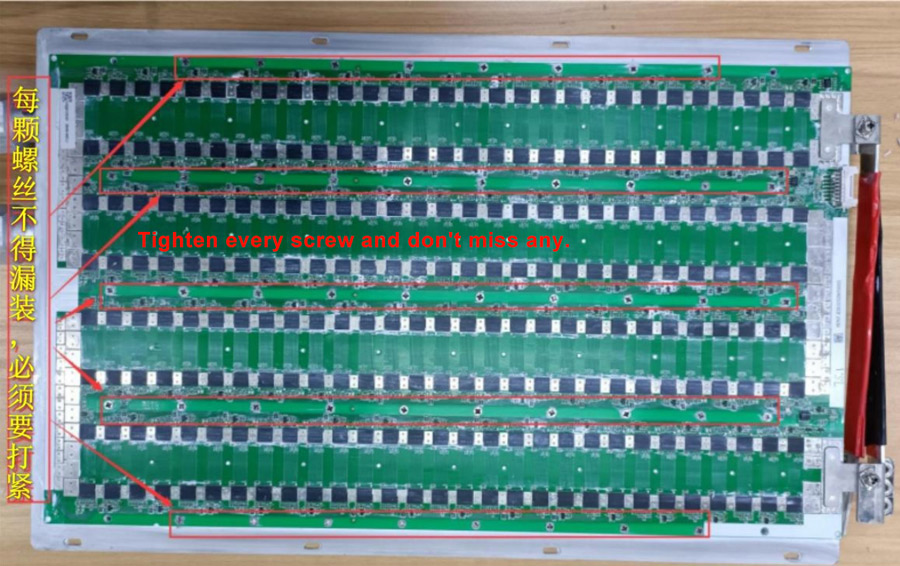
5.2 When installing the hash board to the heat sink surface, ensure that all screws are tightened without missing any to avoid poor local heat dissipation.
6. Fault analysis and troubleshooting
Fault phenomenon | Reason | Troubleshooting |
No hash board recognized | 1. No 3.3V 2. Cannot read eeprom | 1. Check if the 3.3V circuit is short-circuited 2. Check if UC2 is intact |
Unable to read temperature sensor | 1. Poor powering 2. Chip defective | 1. Check the 3.3V power circuit 2. Check if UC1 is normal |
Cannot read chip/ incomplete | 1. RST signal is poor 2. CLK signal is poor 3. RXD signal is poor 4. TXD signal is poor 5. LDO power is poor | 1. The RST signal interruption point is the fault location 2. The CLK signal interruption point is the fault location 3. The RXD signal interruption point is the fault location 4. The TXD signal interruption point is the fault location 5. The LDO signal interruption point is the fault location |
Report high temperature | 1. Chip temperature is too high 2. UC1 reports high temperature | 1. Check whether the screws and thermal grease are properly installed 2. Check whether the water temperature and water flow rate meet the standards |
Low hash rate | 1. Poor powering 2. A certain chip returns less nonce | 1. Check the PSU output voltage. If the voltage is low, replace the PSU. 2. Replace the chip with a lower nonce |
The remaining circuit principles and repair methods are basically the same as those of the air-cooled M30 series hash board. Please refer to the M3X series repair guide.
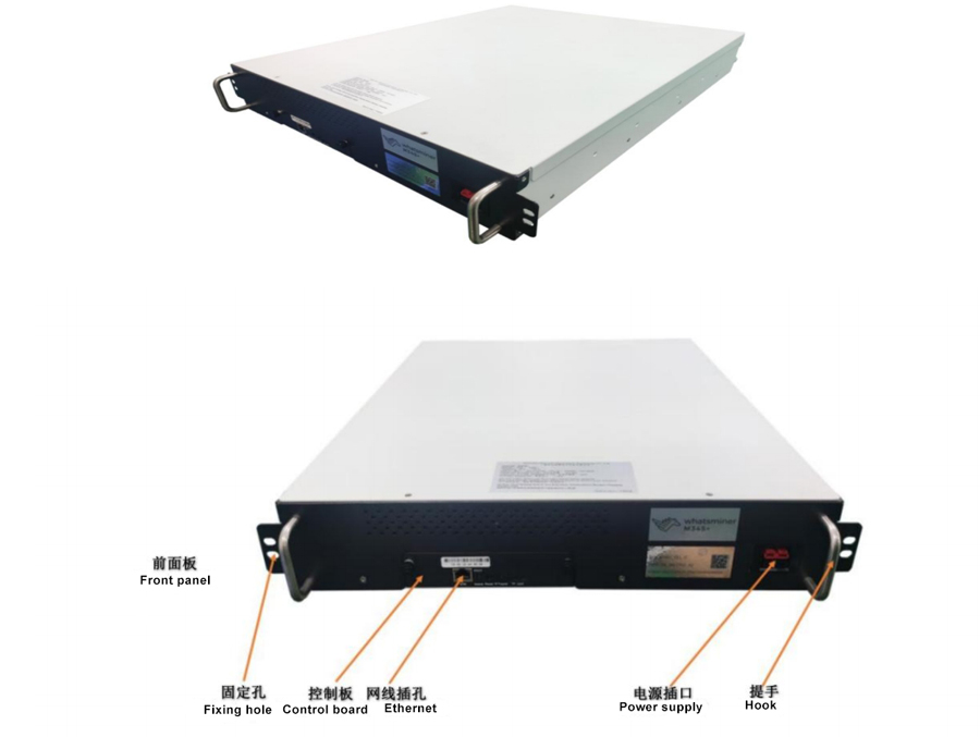
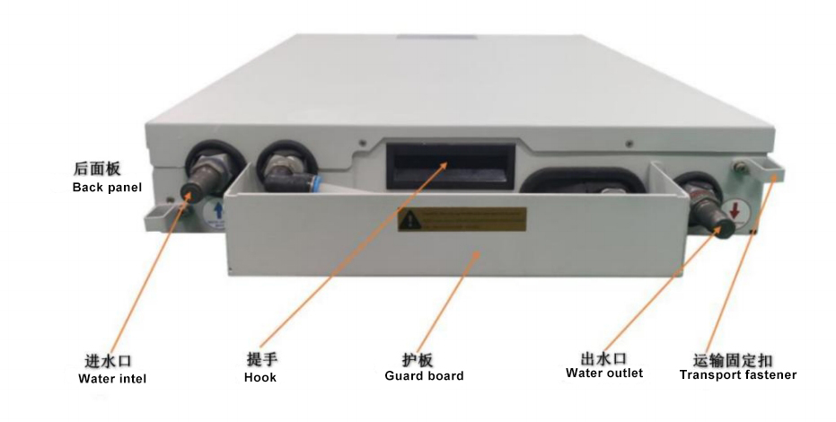
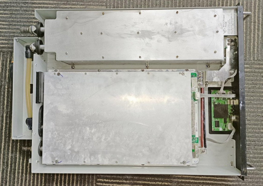
7. Structural diagram
We use cookles to Improve your online experience. By continuing browsing this website, we assume you agree our use of cookies.