


IceRiver KS0 Hash Board Repair Guide
Ⅰ. Maintenance equipment requirements
1. Constant-temperature soldering iron (350-400 degrees): it is used to flatten the residual tin slag on the pad's surface and reinforce the components.
2. Hot air gun: it is used for component mounting and soldering. Be careful not to heat for a long time to avoid blistering the PCB.
3. Multimeter, tweezers, electric screwdriver, temperature gun.
4. Solder wire, flux, board washing water, and tin-absorbing tape; board washing water is used to clean the flux residue and appearance after maintenance.
5. Regulated power supply, fixed voltage 19V, current limiting needs to be determined according to the PCBA status:
PCBA status | Current limiting | Remarks |
Any power network short circuit | 1A | |
No power short circuit / single board test | 4A | Must be assembled in the case and then tested |
Verify performance after repair is completed | 4A | Must be assembled in the case and then tested |
6. Auxiliary components: high-temperature adhesive tape, thermal paste, 5525 male cable;
7. Common materials:
M3*8, cross thin countersunk, black;
M2.5*9.5, fixed spring screw;
Thermal pad, 9*160*0.5MM / 1MM / 1.5MM, 5W/mk.
Ⅱ. Operation requirements
1. After the repair, the hash board must be tested more than twice, and all must be OK before it can pass!
2. After replacing any accessories, the PCB board has no obvious deformation. Check whether missing parts, open circuits, and short circuits are in the replaced parts and the surrounding areas.
3. Check whether the repair tools and test tools can work properly.
4. If there are electrolytic capacitors, LED lights, and plastic plug-ins at the fault point, be sure to protect them with high-temperature adhesive tape to avoid damage.
5. When powering on the hash board, the negative power cable (black in the 5525 male cable) must be powered on first, then the positive power cable (red in the 5525 male cable), and finally, the serial port cable. When disassembling, the order must be opposite to the installation order. First, remove the data cable, then the positive power cable (red), and finally the negative power cable (black), or use the finished 5525 cable for power-on and power-off operations.
Ⅲ. Overall structure and principle
1. The KS0 miner consists of a board that integrates the control board and hash board. Each KS0 consists of 4 ASIC chips. All ASIC chip signals are connected in parallel, and powering is connected in groups of 2.
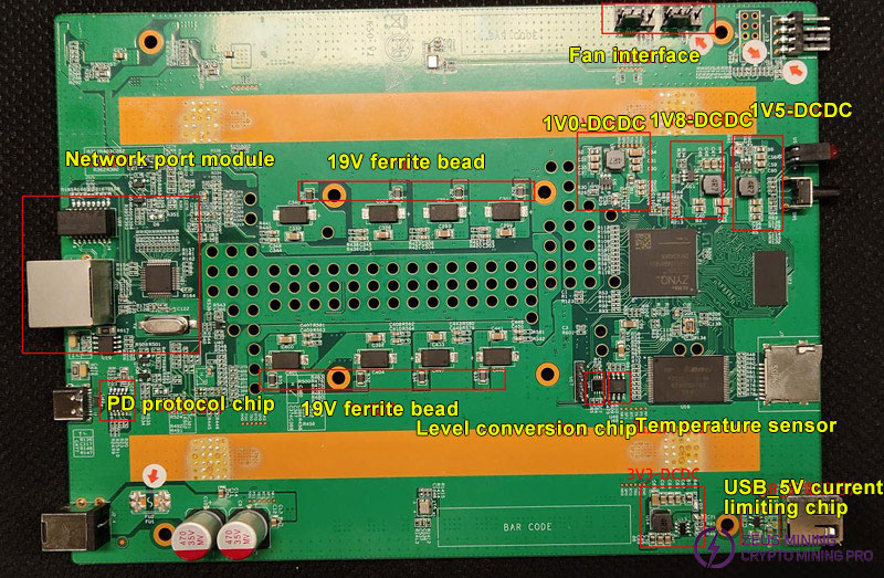
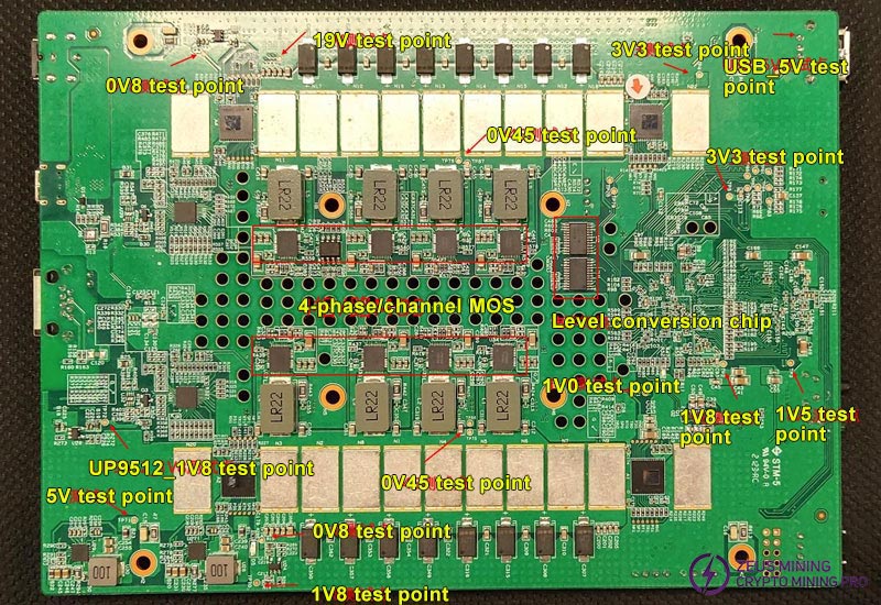
2. Public powering
(1) Chip U29 (Gs9238) 19V→5.0V
(2) Chip U26 (SGM2036-ADJ) 5V→1.8V
(3) Chip U27 (Gs9238) 19V→1.8V
3. The ASIC chip power supply is powered by 3 groups of voltages
(1) ASIC chip main voltage (uP9512 + 4 * uP9650) 0.45V
(2) ASIC chip VDDPST/VDDPLL1V8 voltage (Gs9238) 1.8V
(3) ASIC chip VDD0P8/VDDPLL0V8 voltage (SGM2036) 0.8V
IV. Normal startup process of hash board
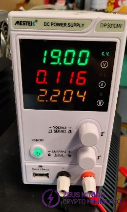
1. The control board part starts first, and the adjustable PSU shows 19V@0.1A. At this time, there is no voltage at the chip 0.45V powering.
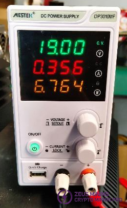
2. The hash board's powering is turned on, and the adjustable PSU shows 19V@0.3A. At this time, there is a voltage at the chip 0.45V powering.
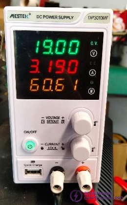
3. The hash board part runs normally, and the adjustable PSU shows 19V@3A, which means that the network connection is successful and the hash board is running normally.
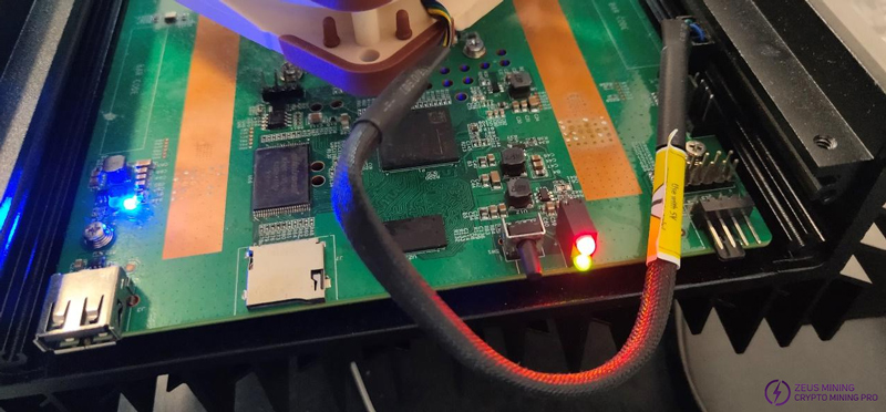
4. About 20 seconds after the control board starts, the red LED is always on, and the green LED flashes, which means that the program is running normally. However, this does not mean that there is no abnormality in the network. If the network connection is abnormal after normal power-on, it will be stuck at step 2.
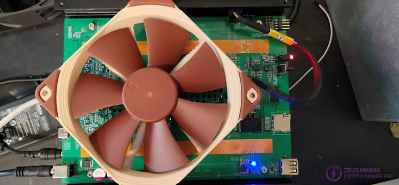
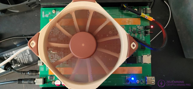
5. KS0 miner at the beginning of power on, after the hash board runs normally, the fan does not rotate. Only when the chip temperature is higher than 65℃ does the fan rotate (a larger fan is replaced as a demonstration for the convenience of the display).
Chip temperature is higher than 65℃:
6. According to the MAC address label on the KS0 board, scan the KS0 IP through the group control software and enter the backend Web.
Default (if login fails, restore the factory settings):
Name: admin
Password: 12345678
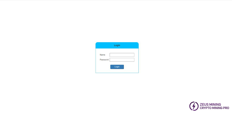
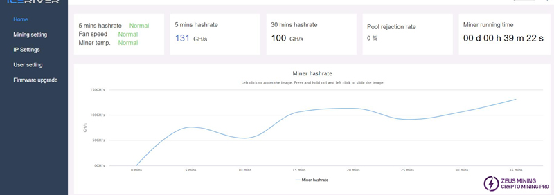
Enter the backend to check whether the miner's hash rate reaches 100G after 30 minutes of operation and whether the Fan speed and the Miner temperature are displayed as Normal.
Regarding the PCB board temperature, the maximum difference between the two temperature sensors on the board does not exceed 15℃.

Depending on the batch, the two fans' speeds are 5000±10%, 6000±10%, and 8000±10%, respectively.

Ⅴ. Common faults and troubleshooting steps for KS0 hash board
The normal power-on current range of the KS0 board is about 0.1A, and after the LED constant, it is 0.3A-0.5A. After the hash rate of the board is running normally, the current is about 3A.
When testing the hash board, the DC adjustable PSU configuration is 19V voltage with a 1A current limit.
1. Phenomenon: The adjustable PSU test shows a short circuit of the current limit when it is turned on. (The current shows 1A, and the voltage is pulled down, less than 19V)
Solution:
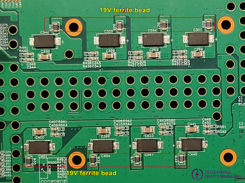
Test whether the impedance is short-circuited at the 19V powering terminal. If the 19V is short-circuited, check each public powering chip, the 4-phase MOS tube and the 19V tantalum capacitor at the MOS tube, which are most prone to failure. Test the MOS tube and tantalum capacitor.
The positioning method is as follows:
Method 1: Use the adjustable PSU to maintain the power-on current limiting state and quickly sense the severely heated area of the board with our hand. If we cannot feel it, we must disconnect each phase to determine whether the 19V is still short-circuited. Locate the faulty chip and replace it; if it is a tantalum capacitor, we need to remove it all and replace it with a new tantalum capacitor. Please do not use an air gun to heat it when replacing it.
Method 2: Disconnect the 19V resistor of a certain circuit, all 4 need to be disconnected. After disconnection, measure the resistance value. If it is normal, it means that the MOS currently disconnected in this circuit has a short circuit.
2. Phenomenon: After powering on, the current is low, the DC adjustable PSU shows 19V voltage and less than 0.1A current, and the two blue LEDs on KS0 are not on (position D3 and D4).

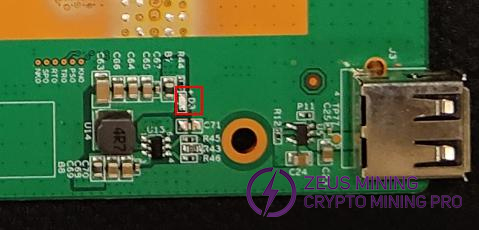
Solution:
Step 1: Check whether 19V is sent to each power input terminal, and check whether there is a 19V powering before and after the 8 Drmos resistors, as well as the 5V public powering, and whether the 1.8V hashing power input is 19V.
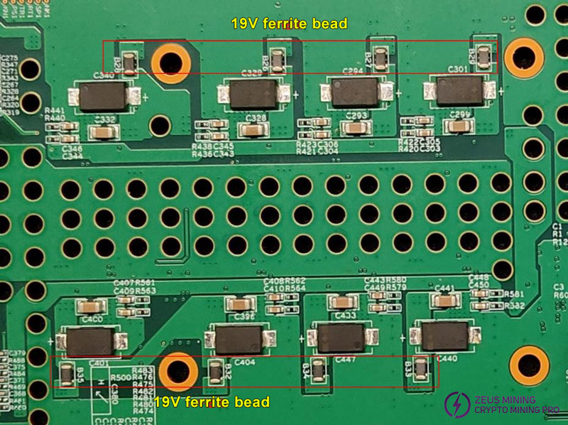
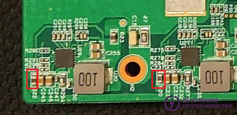
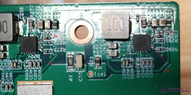
Step 2: Check whether the public powering 5V has output. If there is no output, it is necessary to detect the working status of the GS9238 chip, including the enable voltage and feedback voltage.
Ven>1.6V is considered to be EN success, and Vfb=0.8V is deemed to be normal feedback.
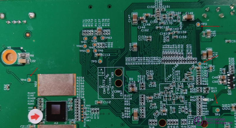
Step 3: Check whether the voltages at TP1, TP2, TP3, and TP4 are 1.0V, 1.8V, 1.5V, and 3.3V respectively.
If any voltage is abnormal, check whether the resistor input, resistor output, EN, and FB voltages of the corresponding chip BL8033 are normal.
Vin=5V or so, Ven>1.5V is considered normal start, Vfb=0.8V.
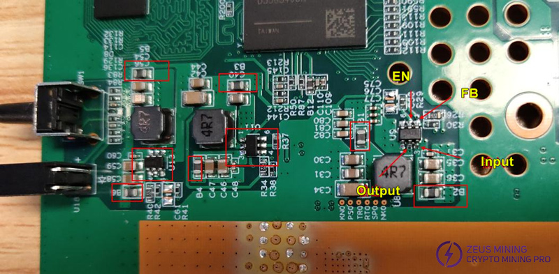
3. Phenomenon: After power-on, the current is low; the DC adjustable PSU displays 19V voltage, less than 0.1A current, and only one blue LED light on (position: D3)
Solution:
Only one blue LED lights up, indicating that there is no abnormality in the control board part's powering, but the system does not start. At this time, we need to check the FLASH soldering or replace the FLASH chip.
4. Phenomenon: During the single board test, only two of the four MOS have high temperatures, and the other two have very low temperatures.
Solution:
Check UP9512's 1.8V powering (B24, B30). When the 1.8V of UP9512 has no voltage, only two MOS are activated.
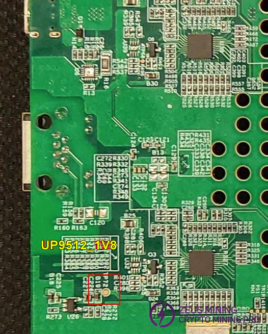
5. Phenomenon: During the single board test, the current is stuck at 19V, 0.3A
Solution:
Check whether the network cable has a good connection with KS0, and check whether this network cable can connect to the external network. After the network is connected normally, the yellow light is always on and the green light flashes.
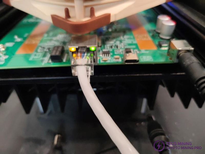
6. Phenomenon: The single board test program is interrupted and the current is high. The DC adjustable power supply displays: 19V voltage, more than 0.5A current or single board test abnormality
Solution:
Check whether the 0.45V voltage output terminal of the chip has a resistance to ground greater than the ground-to-ground resistance. If it is less than or equal to the ground-to-ground resistance, it is necessary to check whether the chip itself is short-circuited.
7. Phenomenon: In the single-board test program, only some chips are displayed, and the current is normal.
Solution:
Step 1: Determine whether the 1.8V and 0.8V voltage of each ASIC chip are powered normally. If they are not normal, it is necessary to determine the voltage disconnection point of each chip and determine the 0.8V-LDO output state.
Specific voltage test points for each chip:
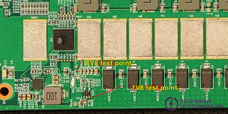
LDO Total Output:
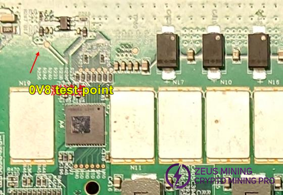
Step 2: Run the single-board test and use a temperature gun to measure the temp of each chip. During the single-board testing, the temp of the ASIC chip is about 40℃ (room temperature 25℃). If some chips reach or even exceed 50℃, and the resistance of the test points on both sides of the chip is abnormal, it is considered that the chip is burned out and needs to be replaced.
Step 3: Measure the resistance of the test points around the chip one by one after the chip is replaced. When the resistance is within the range (as shown in the table), it is considered that the soldering is completed. Attention: the test resistance needs to be measured after the chip temp drops.
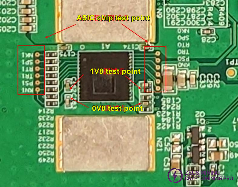
Test point-test point | Resistance |
DIR voltage = 1.8V | |
NK1-NK1 | About 2KΩ |
SP1-SP1 | About 7~12MΩ |
RT1-RT1 | About 12KΩ (chips 1~4 are about 0.4MΩ) |
TR1-TR1 | About 15MΩ (chips 1~4 are about 40MΩ) |
PS1-PS1 | About 7~12MΩ |
KN1-KN1 | About 13MΩ |
DIR voltage = 0V | |
NK-NK1 | About 13MΩ |
SP1-SP1 | About 7~12MΩ |
RT1-RT1 | About 15MΩ |
TR1-TR1 | About 12KΩ |
PS1-PS1 | About 7~12MΩ |
KN1-KN1 | About 2KΩ |
1.8V-1.8V | About 1Ω |
0.8V-0.8V | About 1Ω |
8. Phenomenon: The fan does not rotate or the speed is abnormal

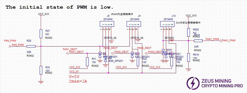
Solution: Check the powering at the fan socket and the level of the PWM control pin.
Pin 1: PWM control signal, the normal voltage is 3.3V, and the fan speed is controlled by the duty cycle
Pin 2: Fan return speed signal
Pin 3: 5V powering
Pin 4: GND
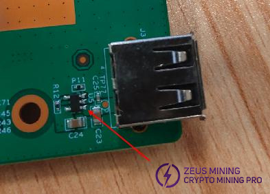
9. Phenomenon: The USB fan does not rotate after being plugged in (the fan speed data will not be displayed in the Web background).
Solution: There is only 5V powering at the USB. The fan has no speed, which means the 5V voltage is insufficient. We need to check whether the 5V voltage at the USB, the input and output voltage of U5 are both around 5V.
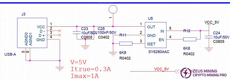
Measure the voltage at the arrow point, or whether the voltage at TP77 is around 5V.
10. Phenomenon: When using Type-C for powering, the input port has only 5V voltage and no 20V input.
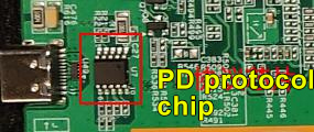
Solution: Check the voltage of the U7 chip pin. If the voltage is within the normal range, check whether the adapter supports the 20V output in the PD protocol; if the powering pin voltage is abnormal, disconnect the series resistor to determine whether the U7 is abnormal and causes the voltage to drop; if the communication pin voltage is abnormal, check the voltage before and after the series resistor.
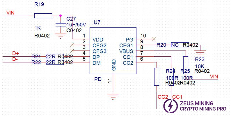
Pin 1 and Pin 8 are the main powering input, Pin 4 and Pin 5 are USB differential signals, and Pin 6 and Pin 7 are PD protocol communication pins.
Test point-test point | Resistance |
Pin 1-GND | 300KΩ |
Pin 2-GND | 16MΩ |
Pin 3-GND | 18MΩ |
Pin 4-GND | 13MΩ |
Pin 5-GND | 13MΩ |
Pin 6-GND | 2.5KΩ |
Pin 7-GND | 2.5KΩ |
Pin 8-GND | 300KΩ |
Pin 9-GND | 20MΩ |
Pin 10-GND | Short-circuit |
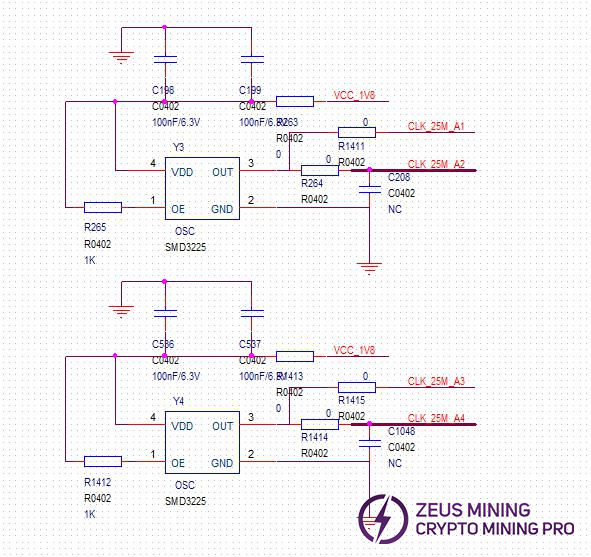
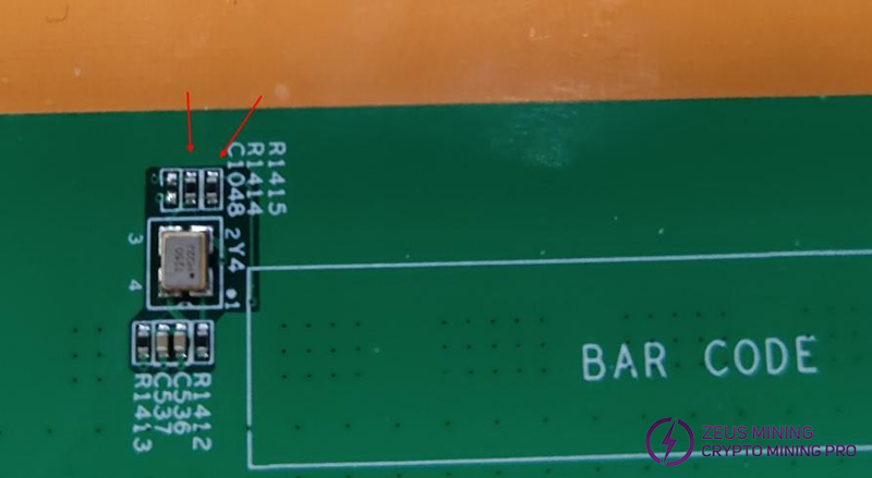
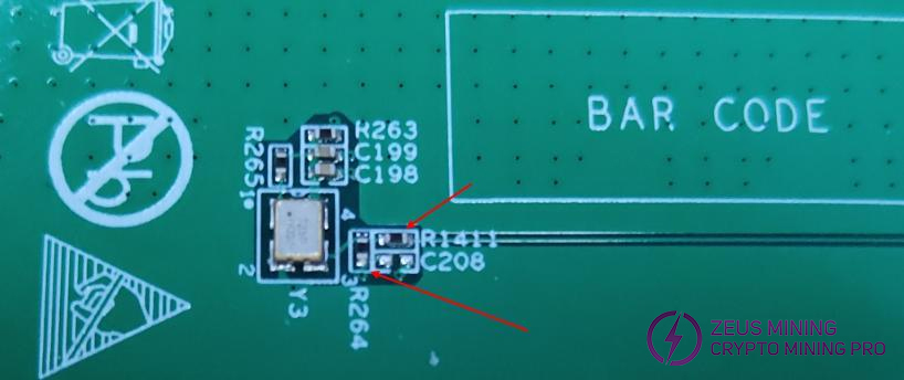
11. Phenomenon: The test program is interrupted or there is no chip, and the serial port pin and powering pin of the ASIC chip are normal, but the voltage of NK1 (Pin 1) is less than 0.9V.
Solution: Check the path from the crystal oscillator to the ASIC chip end, and focus on checking the series resistance of the crystal oscillator end, and check whether the voltage is 0.9V one by one. Check the voltage before and after R1411, R264, R1415, R1414, R214, R227, R234, and R215 one by one.
Ⅴ. Assembly process
Step 1: Use a barcode scanner to scan the barcode on the PCBA of KS0 and record it in the maintenance record.
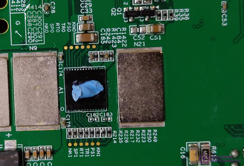
Step 2: Apply thermal grease, the amount is about 2/3 of the chip length, and pay attention to apply the thermal grease on the reflective part of the chip.
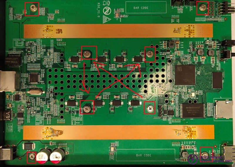
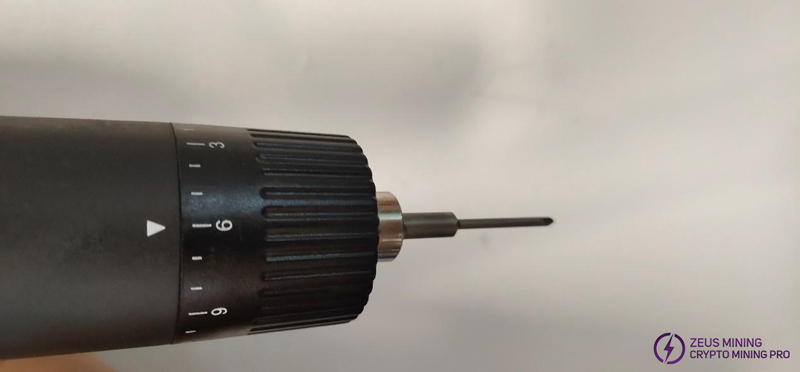
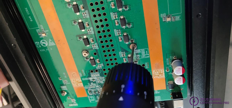
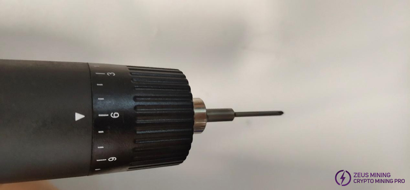
Step 3: Install M2.5*9.5 spring screws and attach black insulating gaskets. There are 8 screws in total. Note that the order of screwing must follow the arrows in the figure, first inside, then outside. Adjust the torque of the electric screwdriver to 6 and drive perpendicular to the PCBA.
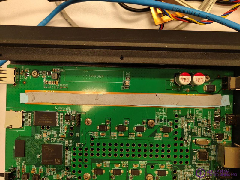
Step 4: Paste the thermal strip, 9*160*0.5MM, first cut the required length of the thermal strip. Remove the protective film on one side and choose any end to paste. Pay attention to evenly cover the surface of the ASIC chip. After pasting, remove the protective film on the other side.
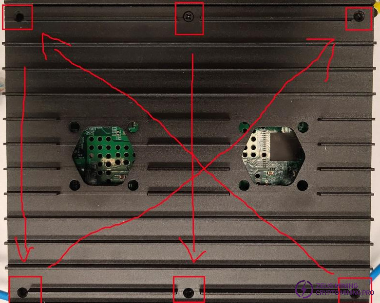
Step 5: Plug in the fan and install the backboard. Use M3*8, cross thin countersunk. There are 6 screws in total. Note that the order of screwing must follow the order indicated by the arrows in the figure, first inside, then outside, and then in the middle. Adjust the torque of the electric screwdriver to 6.
Step 6: Assemble the front and rear boards, and paste the anti-tamper sticker on the 6 screws of the bottom shell.
VII. Other precautions
1. Conventional maintenance process
(1) Observe the appearance
(2) Measure the impedance
(3) Power on and measure the voltage
(4) Power on and test
(5) Determine the fault based on the detection information
(6) Locate the fault and re-solder it first before replacing it
(7) Perform aging test after multiple tests after repair
2. Conventional inspection: First, visually inspect the hash board to be repaired to see if there is any deformation or burning of the PCB. If so, it must be processed first; whether there are obvious signs of burning of parts, parts impact displacement or missing parts, etc.; secondly, after visual inspection, the impedance of each voltage domain can be tested to detect whether there is a short circuit or open circuit. If found, it must be processed first. Thirdly, check whether the voltage of each part is normal.
3. Conventional short circuit detection is necessary to avoid burning chips or other materials due to short circuit when power is on.
4. Unless necessary, generally do not operate the ASIC. If it is determined that the ASIC has failed, it must be powered off. If necessary, remove the corresponding power chip.
5. After the repair is completed, clean the tin slag on the surface of the board and power it on/install it for testing after it cools down naturally.