


Avalon Miner Power Supply Repair Guide
In order to help and guide the site operation and maintenance personnel to improve the repair efficiency and accuracy of the Avalonminer power supply, this repair guide is specially prepared for reference in combination with power supply after-sales maintenance data.
Ⅰ. Scope of application:
| Model | Input | Output | |
| PSU3300-03 | 200-285VAC 50/60Hz 16A Max | 11.5V-14.5V 3100W | 12V 200W |
| PSU3300-03 PLUS | 185-285VAC 50/60Hz 16A Max | 11.5V-14.5V 3100W | 12V 200W |
| PSU3300-01 PLUS1 | 200-285VAC 50/60Hz 16A Max | 11.5V-14.5V 3100W | 12V 200W |
Ⅱ. Basic components of power supply:
1. Electronic components - Resistor
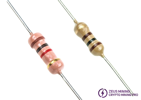
(1) Carbon film resistor
Power: 1/16W~2W
Resistance value: 1Ω~3.3MΩ
Tolerance: ±1%(F)~±5%(J)
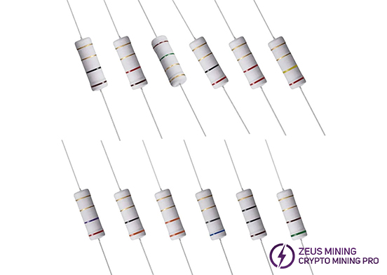
(2) Metal oxide skin film resistor
Power: 1/8W~5W
Resistance value: 5Ω~1MΩ
Tolerance: ±0.1%~±5%(J)
(3) SMD resistor
Power: 1/16W~1/2W
Resistance value: 0Ω~33MΩ
Tolerance: ±5%

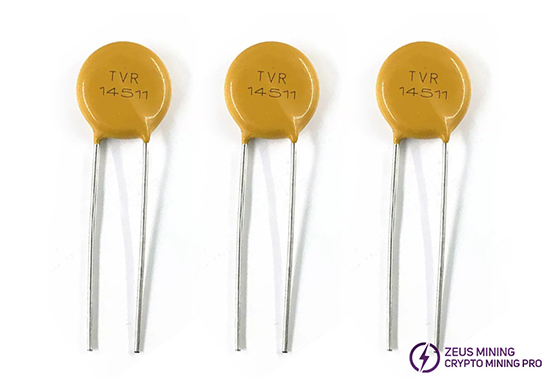
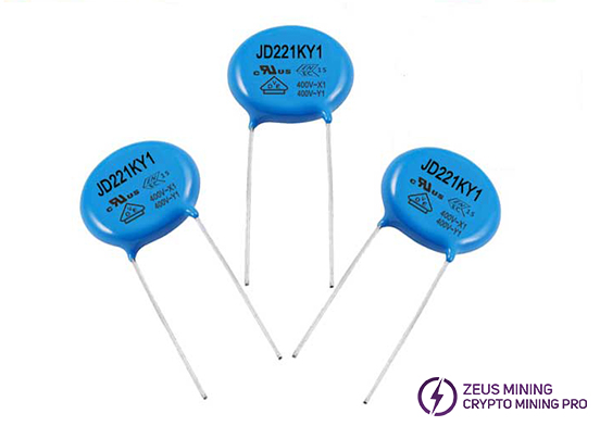
(4) Varistor (safety gauge)
With nonlinear voltammetry characteristics, mainly used for voltage clamp when the circuit is under overvoltage, absorb excess current to protect sensitive devices.
2. Electronic components - Capacitor
(1) Ceramic capacitor
Withstand Voltage: depending on specific specifications
Nominal capacitance: subject to specific specifications
Tolerance: depending on specific specifications

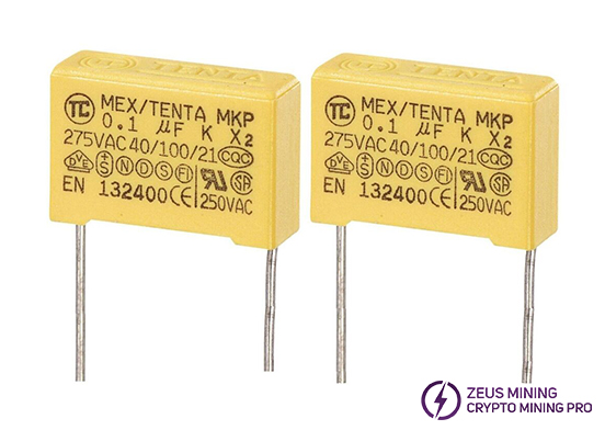
(2) X capacitor: Safety capacitance
(3) Y capacitor: Safety capacitance
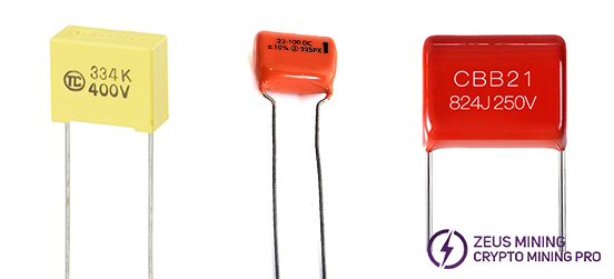
(4) Thin film capacitor: Nonpolar
High insulation impedance and wide range of frequency response
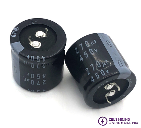
(5) Electrolytic capacitor
Polarity requirements: the long lead is positive and the short lead is negative.
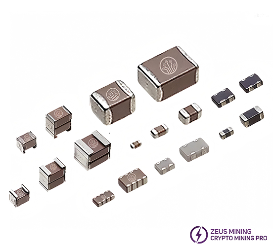
(6) The patch capacitor
Pressure resistance: depending on specific specifications
Nominal capacitance: subject to specific specifications
Tolerance: depending on specific specifications
3. Electronic components - Transistor
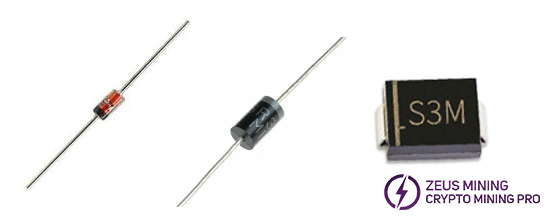
(1) Diode: Rectifier, switch, voltage regulator, etc.
Polarity requirements: ring mark or short pin for the negative pole.
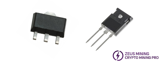
(2) Triode
The main function is signal switching and amplification.
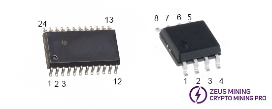
(3) IC: the integrated circuit
Pin number identification: the IC front letter, code to their own, so that the positioning mark (packaging surface has dots or gaps) toward the left below, the bottom left pin is the first foot, the other serial number according to the counterclockwise order.
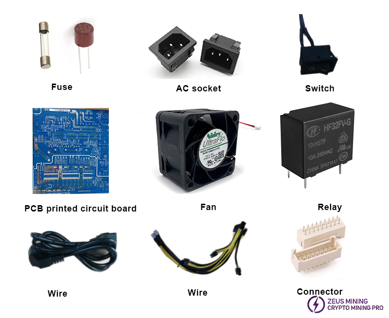
4. Internal structural parts of power supply
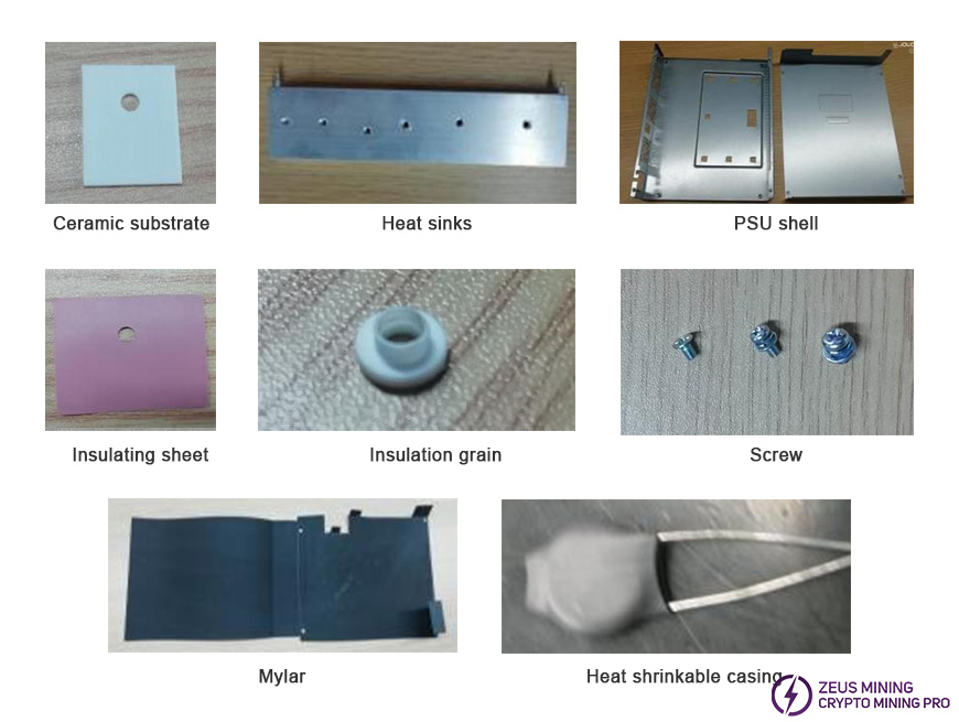
III. Avalon miner power supply working principle
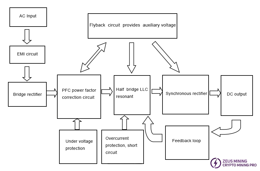
The main circuits of the power supply are: EMI circuit, bridge rectifier,
power correction circuit, flyback circuit, auxiliary half-bridge LLC resonant circuit, auxiliary synchronous rectifier filter circuit, main half-bridge LLC resonant circuit, main synchronous rectifier filter circuit, MCU control circuit, protection circuit.
(1) Power on, the input AC voltage is translated to DC voltage through the EMI circuit and the bridge rectify circuit.
(2) DC voltage generates 18VCC through flyback circuit.
(3) 18VCC is converted to power the relay, auxiliary circuit LLC2 IC, main circuit LLC1 IC, PFC IC.
(4) After the PFC chip works, the PFC voltage is boosted, the main circuit LLC1 IC and auxiliary circuit LLC2 IC begin to work.
(5) After the main output LLC1 chip works, there is a main output voltage through LLC resonant circuit, and then the synchronous rectification works;
(6) After the auxiliary circuit LLC2 IC works, there is a auxiliary output voltage through LLC resonant circuit, and then the synchronous rectification works;
(7) The auxiliary voltage is translated to power the MCU IC, Which provides software communication, control, protection function.
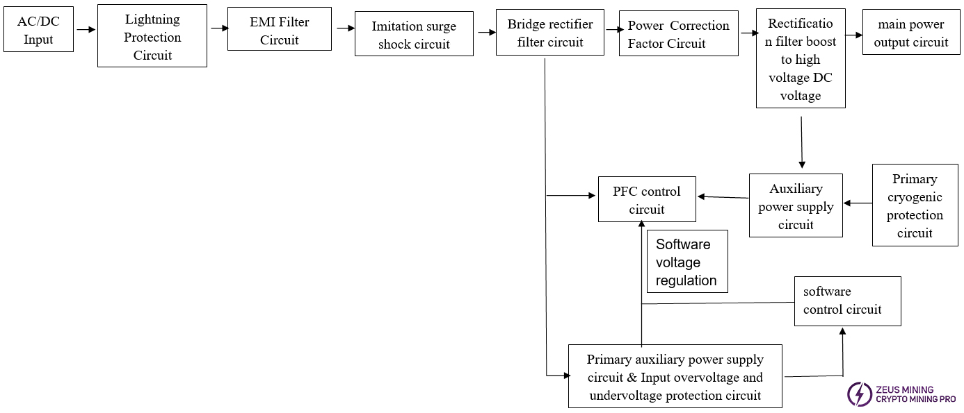
IV. Power supply circuit diagram
1. For PSU3300-03 and PSU3300-03 PLUS
2. PSU3300-01 PLUS1
Ⅴ. Common failure analysis and maintenance
For PSU3300-03 and PSU3300-03 PLUS
1. Hardware failure
(1) Analysis process
①. Fault type determination, the specific method is:
a. If the power supply is cut off, remove it from the miner.
b. Short circuit the 2Pin on the right of the terminal (near the V+ terminal), as shown in figure:
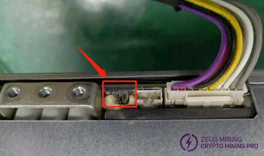
c. Power on the power supply unit, not connected to the miner.
d. Multimeter set the DC voltage range and measure the output voltage of the power supply.
Connect the positive terminal of the multimeter to the PSU terminal "+" and the negative terminal to the PSU terminal "-":
If voltage ≥ 11.9V, the power supply hardware is preliminarily determined to be OK, to be confirmed by machine aging;
If voltage < 11.9V, it is preliminarily determined that the power supply hardware is faulty.
② Hardware troubleshooting:
a. The power supply has no output maintenance process:
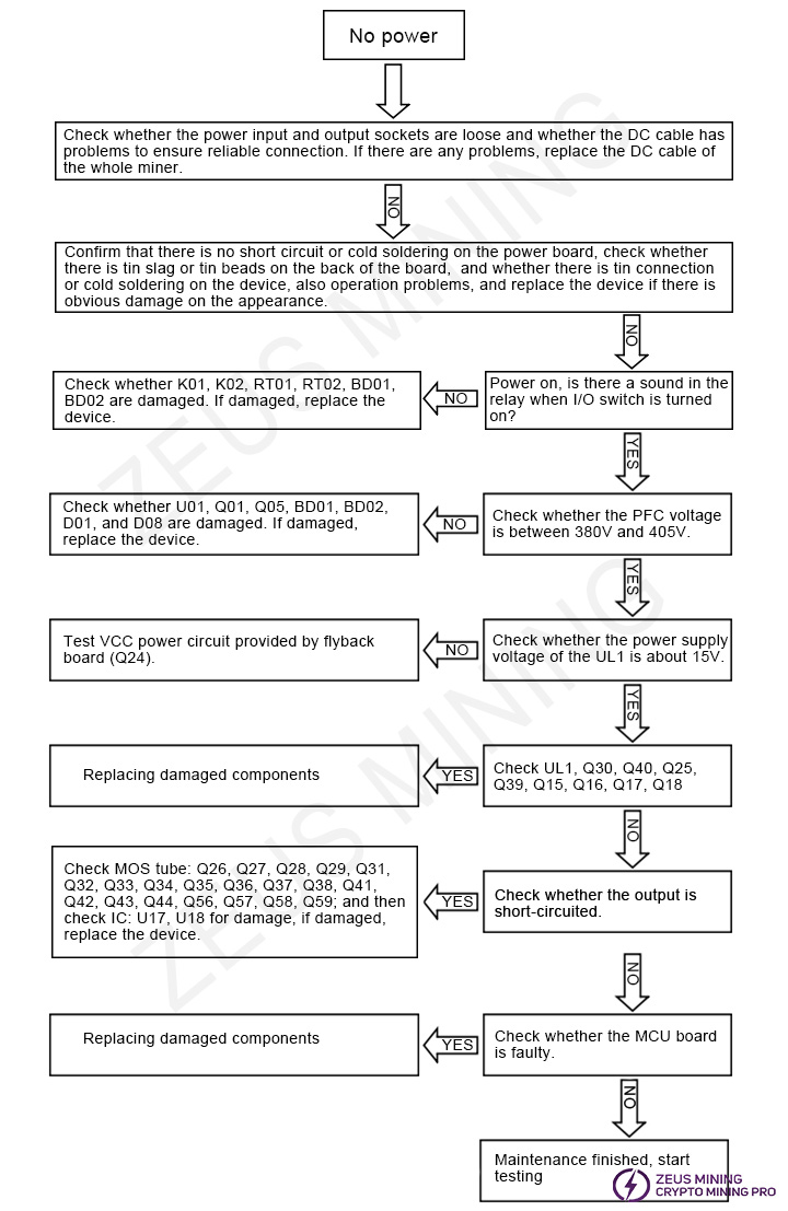
(2) Maintenance method
Phenomenon | Bad Reasons | Repair method |
No output | F01 open | Cause details: Overvoltage or overcurrent power abnormality, causing AC fuse F01 to blow. Repair method: Set the multimeter to the diode gear and measure the AC socket L and N lines. If no value is displayed, F01 is open; if there is a value displayed, it means that the AC line is normal. |
High-voltage BUCK small board damaged | Cause details: The high-voltage BUCK board was damaged due to the harsh working environment. Repair method: Check whether the chips UF1, QF1, QF2, RF9, RF10, RF17, RF18, RF19 and RF14 are damaged. If damaged, replace the device. | |
BD01 or BD02 is damaged | Cause details: AC bridge rectifier diodes BD01 and BD02 were damaged due to excessive dust. Repair method: Replace BD01, BD02, and F01. Pay attention to replacing the device to cover the well casing. The four pins of the bridge rectifier diode must be sleeved, and thermal paste must be applied between the radiator and the diode. | |
BD03 is damaged | Cause details: The pin of the small bridge rectifier diode BD02 is corroded and damaged. Repair method: Replace BD03. | |
Fan is damaged | PFC partial blast machine: Check whether U01, Q01, Q05, BD01, BD02, D01, D08, Q02, Q07, Q03, Q08, F01, D02, D09, and peripheral SMD resistors are damaged. If damaged, replace the device. When replacing BD01, BD02, Q01, Q05, D01, and D08, pay attention to applying thermal paste, and when replacing F01, pay attention to putting on heat shrink tubing. To determine whether chip U01 is damaged, set the multimeter to the diode measurement gear and detect a voltage difference of about 0.5V between VCC and ground. If not, replace U6 (IC: NCP1654). | |
Main LLC partial blast machine: Check Q30, Q40, Q25, Q39, Q15, Q16, Q17, Q18, UL1, R1, R2, R16, R18, D9, D12 for damage, if damaged, replace the device. When replacing Q1 and Q8, be sure to apply thermal paste. When measuring whether chip U2 is damaged, set the multimeter to the diode measurement gear and check whether there is a voltage difference of about 0.5V across C94. If not, replace U2 (IC: NCP1399AM / 1399AC). | ||
Synchronous rectification MOS is damaged | Cause details: Corrosion of components/circuits causes short circuits of synchronous rectification low-voltage MOS. Repair method: Check whether Q26, Q27, Q28, Q29, Q31, Q32, Q33, Q34, Q35, Q36, Q37, Q38, Q41, Q42, Q43, Q44, Q56, Q57, Q58, Q59, U17, U18, Q45, Q46, Q47, Q48, Q49, Q50, Q52, Q75, and resistor 2R2 are damaged. If damaged, replace the device. There are five synchronous rectification MOS tubes in a group. Generally, only one is damaged, so it needs to be carefully inspected. Note: After replacing the MOS tube, re-apply the thermal paste before locking the heat sink. | |
No start up | Auxiliary LLC2 small board is damaged | Cause details: Strong voltage breaks down the auxiliary small board circuit. Repair method: Check whether Q16 and Q11 are short-circuited. If so, replace the device. Check whether the impedance of the VCC of the chip UL2 to the ground pin (pin 5) has a voltage difference of about 0.5V. If not, or it has been short-circuited to the ground, replace UL2 (IC model: 1399AM/1399AC). Note: After replacement, reapply the tri-proof paint. |
Remark: ① Fan damage will cause the PSU temperature to rise too high, resulting in the explosion. Component damage can be divided into two parts: PFC part explosion and LLC part explosion. Each part should be measured separately during analysis. ② When replacing materials, the corresponding model must be used. Do not think it is the same material by looking at it with the same appearance. | ||
2. Software failure
(1) Analysis process and fault type determination
a. Turn off the power supply and remove it from the whole miner;
b. Short-circuit the 2 pins on the right side of the terminal (near the V+ terminal), as shown in the figure:

c. Turn on the power supply unit without connecting the miner;
d. Set the multimeter to the DC voltage gear and measure the power supply's output voltage. Connect the positive pole of the multimeter to the power terminal "+" and the negative pole to the power terminal "-".
If voltage <11.9V, it is preliminarily determined that the power supply hardware is faulty. The analysis process and repair method are as described above.
If ≥11.9V, it is preliminarily determined that the power supply hardware is OK. Next, the PSU is connected to a qualified miner (hash rate, power consumption ratio and other indicators are qualified) and normal running aging.
If there is still no hashrate, low hashrate, abnormal PS data, or other related error codes, it is preliminarily determined that the PSU software circuit is faulty;
After connecting the miner, if the aging hashrate, power consumption ratio, and other indicators are normal, the power supply is OK.
(2) Repair method
Troubleshoot the MCU board STM8S005C6T6 IC chip, resistor, and capacitor components one by one and replace them accordingly.
For PSU3300-01 PLUS1
1. Repair and Maintenance
(1) PSU troubleshooting
a. PSU introduction
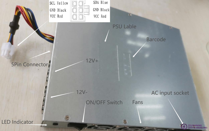
b. Product appearance inspection and testing
① First, observe the appearance to see if there is obvious damage. If there is an obvious appearance problem, it can be impacted or dropped.
② Secondly, shake to see if there is any abnormal sound. If there is any abnormal sound, the power tube may blow up.
③ Measure the input and output impedance with a multimeter again to see if there is a short circuit, whether the input terminal is loose or arcing, and whether there is a short circuit between L / N / G. The output terminal of the 12V main circuit is deformed, short-circuited with the shell. The short circuit between positive and negative electrodes is measured. 12V auxiliary circuit output terminal is damaged, and there is a short circuit between pin pins, and a short circuit between positive and negative poles is measured.
④ Check if foreign objects block the fan blades;
⑤ Power on the PSU, short-circuit the AGND and SETUP of the 5Pin terminal can start the main circuit output;
⑥ Observe the indicator light on the front panel. The green light is on for normal operation, and the red light indicates an abnormality, and the input voltage must be disconnected immediately;
⑦ Power on the PSU and observe the indicator light inside it:
1) The indicator light is always on: the output fan is faulty.
2) The indicator light flashes once and goes out for 3S: ambient temperature is too high for protection.
3) The indicator light flashes twice and goes out for 3S: secondary heat dissipation temperature protection.
4) The indicator light flashes 3 times and goes out for 3S: LLC heat dissipation temperature protection.
5) The indicator light flashes 4 times and goes out for 3S: PFC heat dissipation temperature protection.
⑧ If there is no response after powering on, open the cover and discharge the capacitor.
1) Open the input control switch (0: off, 1: on), and measure whether the switch is closed normally;
2) Observe whether there is a blown power tube or burned device inside the PSU;
3) Measure the main power tube to see if there is any damage.
⑨ Power on the bare metal: measure key voltages
1) Large electrolytic capacitor voltage: about 390V
2) Primary auxiliary power VCC power about 15V
3) Auxiliary output power 15V
4) Auxiliary 12V
5) Main circuit default output 13V
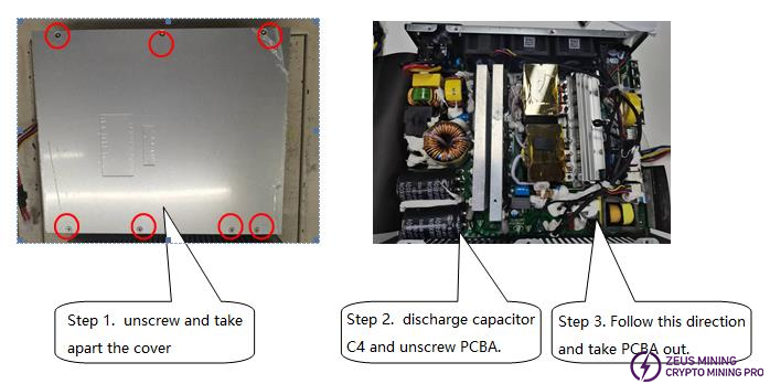
(2) Flowchart of disassembling the casing of the whole machine
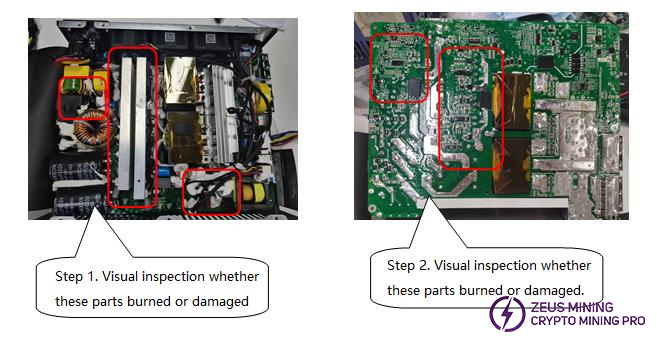
(3) Determination of defective PCBA appearance
(4) Flowchart for analyzing PCBA hardware failure
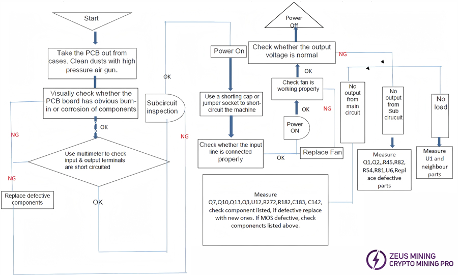
(5) Method of detecting defective products using a multimeter
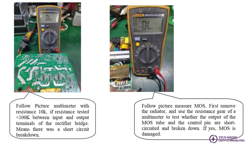
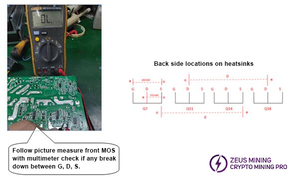
2. Common fault analysis and repair
(1) BOM list of common fault failure components
Failure | Location | Main defective parts | Parts to diagnosed |
PFC voltage no 390V | PFC circuit | TR1 short circuit | F2, RB1, RB2, RT1, D5, D9, D13, Q32, Q33, Q34, R311, R309, R314, R329, R330 some of these parts fail. |
PFC voltage no 390V | PFC circuit | C4, C24 fail | / |
No output | 13V MOS circuit main drive | Q10, Q13, Q3, Q7 short circuit | U7, U19, U12, RT1, D5, D9, D13, R329, R330 some of these parts fail. |
No output | 12V output MOS drive circuit | Q1, Q2 short circuit | U6, Q21, Q23, R53, R56, R87, R110 some of these parts fail. |
No output | 13V main output circuit | Q6, Q8, Q9, Q11, Q12, Q14, Q15, Q16, Q17, Q18, Q19, Q20 fail | Some of these parts fail, G/D/S short-circuit |
Main output high ripple | 13V main output circuit | C31, C32, C40, C41, C46, C47, C48, C49, C51, C52, C55, C56, C57, C59, C60, C62, C63, C64, C65, C66, C70, C71, C72, C73 | Some of these parts fail, capacitance value decay. |
No output | 12V output circuit | Q22, Q24 fail | Some of these parts fail, G/D/S short-circuit |
No output | Fan | The fan blade is blocked, or the fan cable is corroded and opened. | / |
No output | Input circuit | NO / OFF Switch fail | / |
No output | 12V output cable | 12V output cable damaged or fell off. | / |
(2) Common faults and repair methods
Phenomenon 1: No output
Repair method:
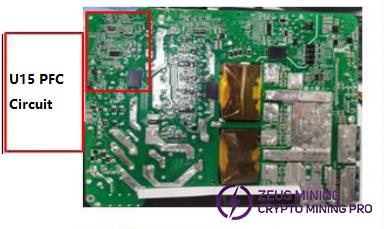
Step 1. Check whether the C4 capacitor voltage is 388V to 420V. If no, check the circuit near U15 to see if there is 14V.
Step 2. The 14V is powered by U10, U7, and U6. If normal, check whether the output MOS is short-circuited. If not, check whether the front-stage MOS tube and nearby circuits are normal.
Phenomenon 2: No main output
Repair method:
The auxiliary circuit is normal, and the main circuit has no output. Check whether the 7th pin of the communication board has 1.5V. If so, it means the communication signal is normal. Check whether input and output MOS tubes are short-circuited, whether the components near U12 and U19 are normal, and whether the PFC voltage is normal.
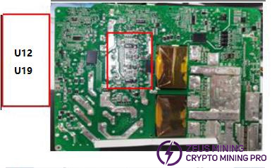
Phenomenon 3: No IIC communication output
Repair method:
First, make sure that the auxiliary circuit of the machine has a 12V output and short-circuit AGND and SETUP with a short-circuit cap to start the main circuit. The output voltage is normal, indicating that the power supply of the miner is normal.
It is necessary to check whether the output 6P cable is damaged and the cable sequence is correct.
If it is correct, check whether the components around the U14 chip are damaged and use a multimeter to connect DAT and CLK to the ground resistance value is correct.
If it is incorrect, it can be judged that it is a problem with U14 and nearby circuits. If the resistance value is correct, it is necessary to check whether U17 and the nearby circuit and power voltage are normal. If the program is lost, it will not communicate.
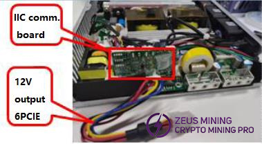
Phenomenon 4: PSU fail
Repair method:
Measure C12, C17, C31, C32, C40, C41, C46, C47, C48, C49, C51, C52, C55, C56, C57, C59, C60, C62, C63, C64, C65, C66, C70, C71, C72, C73.
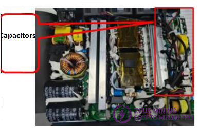
Phenomenon 5: PSU no output
Repair method:
Step 1. Check whether the ON/OFF switch fails or not.
Step 2. Is the F1 fuse broken or not?
Step 3. C4 capacitors voltage within 388-420V
Step 4. Measure with a multimeter to check whether input MOS failed or not.
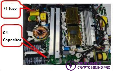
VI. Repair tools and materials
Repair tools | Specifications | Power |
Soldering Iron | 150W | |
Hot air gun | 100w | |
Absorb gun | / | |
Tweezers | / | |
Brush | / | |
Long nose pliers | / | / |
Pliers | / | / |
Multimeter | / | / |
Wire stripping pliers | / | / |
Electric screwdriver | / | |
Tin wire | / | |
Screwdriver | / | |
Discharger (light bulbs) | / |
Ⅶ. Maintenance precautions
1. When checking the bad power supply, be sure to use the protection switch to avoid damage from an explosion.
2. Pay attention to electrostatic protection during maintenance and wear an anti-static wristband.
3. For the temperature management of the soldering iron, it is recommended to control it at 380℃~420℃.
4. The same model and specification products should be used to replace maintenance materials.
5. The defective materials replaced during maintenance must be marked as faulty, and the on-site positioning management should be optimized to avoid mixing with qualified products.
6. Record the power supply S/N serial number, defective phenomenon, defective cause, maintenance method, and other information, and provide maintenance record sheets regularly.