


Edition Date: 2019-09-05
File category: Maintenance program
Content of this volume: mainly describe how to troubleshoot various faults of the APW9 + power supply, and how to use test testers for accurate positioning.
I.Requirements for Maintenance Platform
1. Constant temperature soldering iron, above 80W (soldering temperature is 300-350℃), pointed soldering iron tip is used to solder small patches such as resistors and capacitors, etc., knife-type soldering iron tip is used for replacing plug-in component by welding (welding temperature is 380- 420 ℃).
2. The heat gun is used for chip disassembly and soldering. Be careful not to heat it for a long time to avoid PCB blistering (welding temperature is 260 ℃±2 ℃).
3. AC controllable power supply voltage regulator (output 200-250V, limit current 0-20A) is used for APW9 + power-on inspection. If it's not available, operator can also connect a 100W ordinary light bulb to the utility AC live wire, but shall pay attention to safety.
4. Electronic load (power 3.6KW, suitable voltage 0-50V); if it's not available, operator can make a power resistance load matching APW9 +.
5. Multimeter (recommend to use Fluke 15b+ multimeter), suction gun, camera, V9-1.2 testers and special power supply test card firmware (configure an oscilloscope if available).
6. Flux, lead-free solder wire, water for cleaning panel and anhydrous alcohol; water for cleaning panel is used to clean up the residue and appearance of the flux after maintenance.
7. Thermally conductive silicone grease (2500) is used to repair the heat conduction between the MOS and the heat sinks. The thermally conductive silicone (704 silicone) is used to fix the cover after the original glue of the PCBA component is damaged after repair.
II.Requirements for Maintenance Operations
1. Maintenance personnel must have certain electronic knowledge, more than one year of maintenance experience, have a certain
understanding of the working principle of switching power supply, and master the welding technologies.
2. Before opening the shell and repairing the PCBA board, the large capacitor must be discharged. After the voltage is measured with a multimeter (if it's less than 5V, discharge is completed), the welding operation can be performed! Please pay attention to confirm to avoid electric shocks.
3. Pay attention to the operation methods when judging circuit components. After replacing any device, there shall be no obvious deformation of the PCB board. The soldering of the bonding pad is reliable. Check the replacement parts and confirm whether there are few open and short circuits around them.
4. After the replacement of the key components, the main circuit is checked and measured to have no short circuit and other obvious abnormalities before the AC voltage test, otherwise there may be a hidden danger of machine explosion.
5. When AC220V voltage is needed to judge the circuit signal, please pay attention to operation protection.
Precautions:
● The qualification of maintenance personnel must meet the specified requirements.
● The instruments and equipment used for maintenance must meet the specified requirements.
● The repaired instruments and equipment must be effectively grounded, and the maintenance environment requirements should meet anti-static (It is recommended to wear an anti-static wrist strap during maintenance.) requirements.
● The materials used for maintenance must meet the specified requirements; in order to ensure the accuracy and traceability of the materials used for maintenance, the materials used for maintenance must be the production materials of the corresponding models, and the requirements for material replacement must be confirmed;
● In order to prevent possible electric shock hazards, non professionals are not allowed to disassemble the shell;
● The maintenance personnel need to use a special shelling machine to repair the power adapter, so as not to damage the internal components of the product;
● After the product is opened, it is required to discharge the high voltage capacitor;
● Electronic waste generated during product maintenance cannot be discarded at will;
● Defective products must be marked on the repair process card and placed in a partition;
● The repaired products must be marked to distinguish;
● The repaired products must be placed in the repaired area and require systematic testing before they can be put into storage.
III.Principle and Structure of Power Supply
I. Overview of principles
1. APW9 + is composed of a large board, three fans and a lower shell. Normally, two inputs are connected to AC220V. It has two DC output voltages, respectively SB12V. The main voltage output 14.5V 21V is controlled by PIC port and miner communication.
2. APW9+ performance properties and range of use.
The APW9+ power supply is a high-efficiency DC power supply. It has a single-phase AC input and two DC outputs.
(1) 14.5V-21V voltage adjustable output (output 1), the maximum current can reach 170A;
(2) 12V voltage fixed output (output 2), the current can reach 12A.
Voltage adjustable output (output 1) can satisfy the common DC load within 170A current in the adjustable voltage range, especially suitable for the field of servers and mining machines which require a strict power supply; 12V voltage fixed output (output 2) can satisfy the use of controller panel and cooling fan.
①. It has the following characteristics:
1) 200-240V wide voltage input.
2) There is under-voltage, short-circuit, overload and over-temperature protection inside, which can be automatically recovered after the fault is removed.
3) The selection of high-quality devices designed through reasonable schemes ensures the stability and reliability of the product, which can work with a full load in a high-temperature environment of less than 50℃ for a long time.
4) Density of small size and high power.
3. APW9+ Exterior Design Introduction
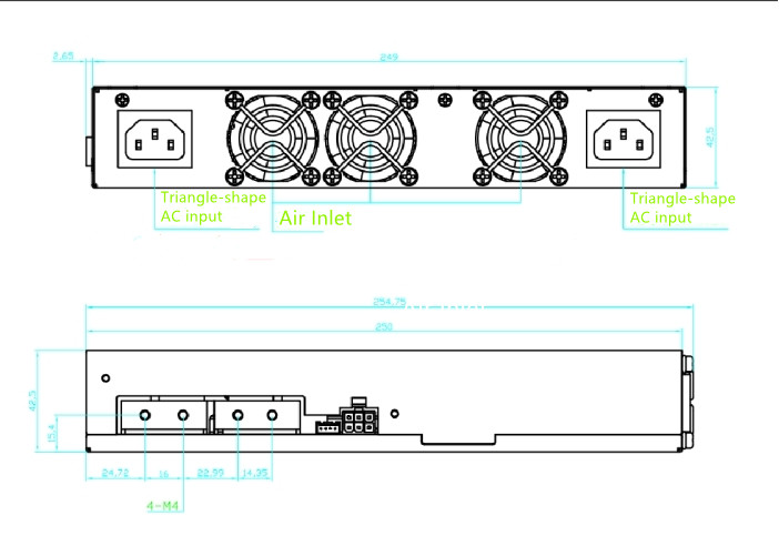
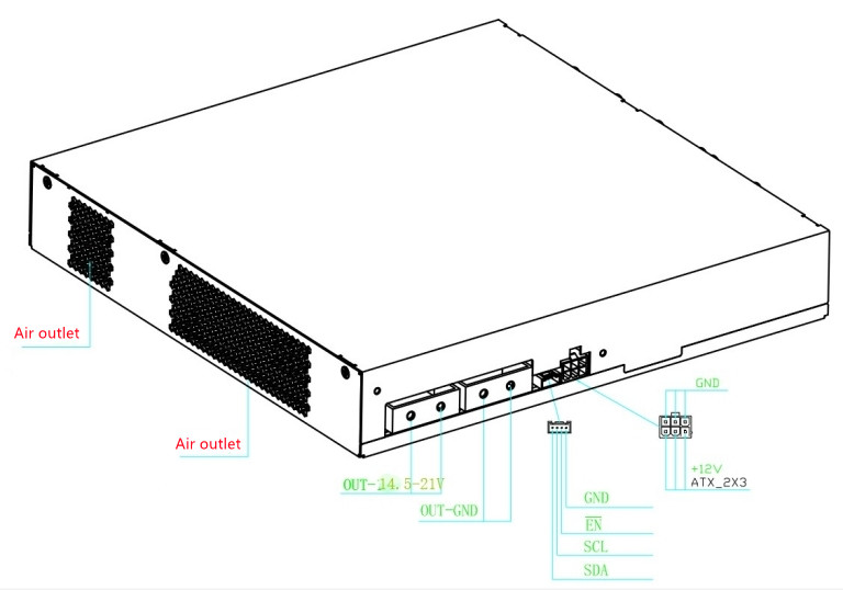
Note: If operator needs to start up to test the default voltage of 21.32V, operator can use a patch cord to short-circuit the pin EN and GND of the voltage regulation port.
The actual product shall prevail. The following is the APW9 + housing with two ports.

● Power supply distribution on the front panel: two triangle-shape AC input interface; 3 4028-size high-speed fans.
● Power supply distribution on the left side: 4 PCB-33 copper welding terminals with adjustable voltage output; one 4-Pin signal terminal; 1 PCIE terminal with 12V fixed voltage output.
● Power supply distribution on the back panel: heat dissipation outlet, which constitutes the outlet of high-speed fan.
● The type of AC input terminal on the front panel of power supply is C14, which needs AC input cable with C13 interface.
● The 4-Pin signal terminal is the communication interface between the external controller board and the power supply. SDA/SCL is I2C protocol, which can adjust the output voltage of the power supply through I2C. EN is the enable signal of power supply, and the power supply of controller board can be enabled by EN, which is effective at low level.
● The adjustable voltage output (output1) uses 4 PCB-33 copper welded terminals, 90 degrees side-foot terminal, and M4 high current horizontal fixed socket; 2 terminals near the outlet are output positive poles, 2 terminals near the signal terminals are output negative poles, and output wires or output copper bars can be fixed by M4 screws on the terminals etc. for easy and flexible use.
● 12V fixed voltage output(output2) adopts PCIE output terminal.
● The PCIE output terminal diagram is shown below:
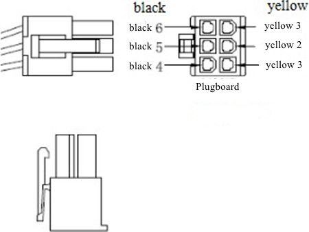
The PCIE output cables consist of two colors: the 12V positive cable is yellow, the negative cable S is black.
6-PIN PCIE Positive and Negative Output Terminals:
Positive: Yellow 1, Yellow 2, Yellow 3
Negative: Black 4, Black 5, Black 6
4. APW9+ specifications:
| Output 1 | DC Voltage | 14.5V-21V |
| Rated Current(200-240V input) | 170A | |
| Rated Power(200-240V input) | 3600W | |
| Ripple & Noise | <1% | |
| Line Regulation | <1% | |
| Load Regulation | <1% | |
| Setup Time | <2S | |
| Short Circuit Protection | >10mS | |
| Output 2 | DC Voltage | 12.3V |
| Rated Current(200-240V input) | 12A | |
| Ripple & Noise | <1% | |
| Voltage Accuracy | 12.2V---12.4V | |
| Line Regulation | <1% | |
| Load Regulation | <1% | |
| Setup Time | <2S | |
| Short Circuit Protection | >10mS | |
| Input | Voltage Range | 200-240V AC(For two inputs) |
| Frequency Range | 47-63Hz | |
| Power Factor | >0.99(full load) | |
| Leakage Current | <1.5mA(220V 50Hz) | |
| Protection | Low-voltage Input | 80-89V AC |
| Output Short Circuit | Yes | |
| Over-current Output | 180-230A | |
| Overheat Protection | Yes | |
| Environment | Operating Temperature | -20-50℃ |
| Operating Humidity | 20%-90%RH(non-‐condensing) | |
| Altitude | < 2000m | |
| Structure | Dimensions | 249*250*48.5mm |
| Net Weight | about 3.2Kg | |
| Cooling System | forced-‐air cooling | |
| Noise | 67dBA |
II. Maintenance ideas and cases of common faults
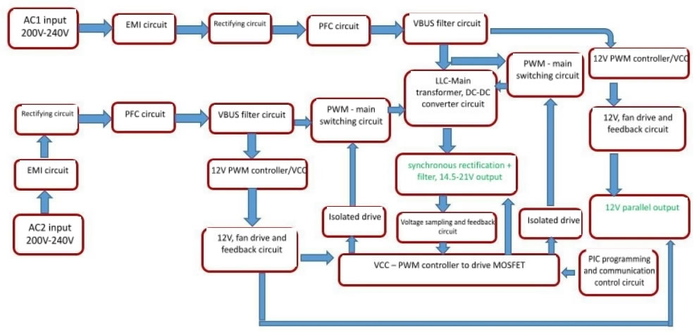
1. Block diagram of power supply basic principle
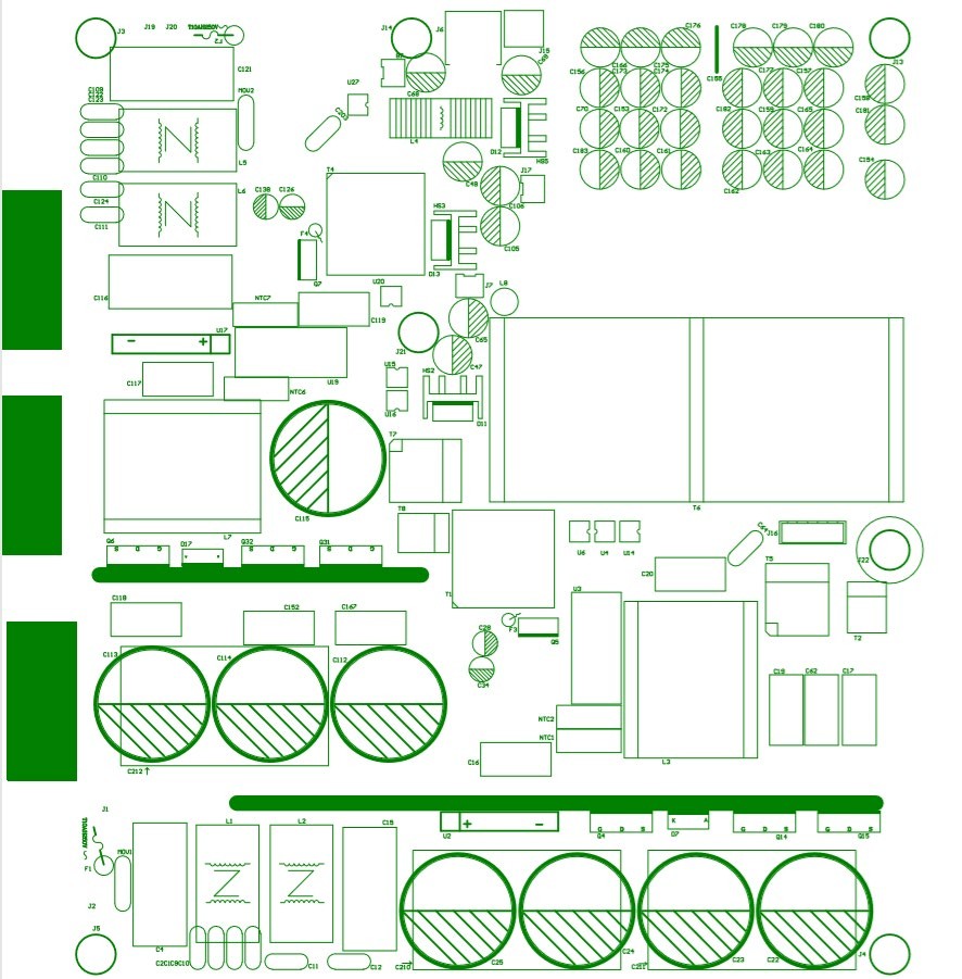
2. Power PCBA board layout
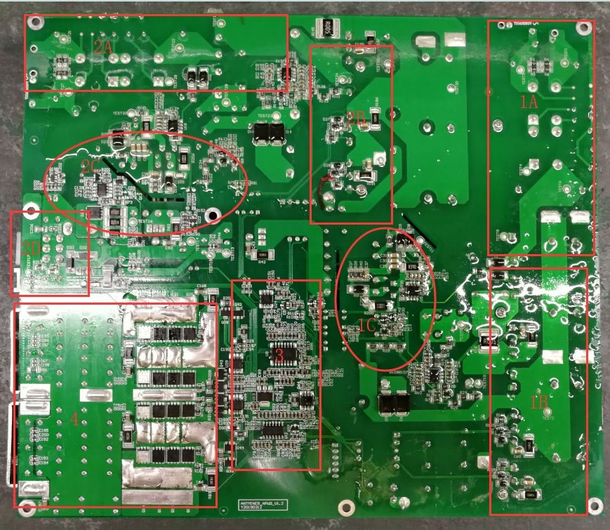
Layout marking instructions:
1A --- the first circuit AC input and EMI circuit;
1B --- PFC and main switch MOS circuit;
1C --- 12V auxiliary and VCC circuit.
2A --- The second circuit AC input and EMI circuit;
2B --- PFC and main switch MOS circuit;
2C --- 12V auxiliary and VCC circuit;
2D--12V output port and PIC communication port.
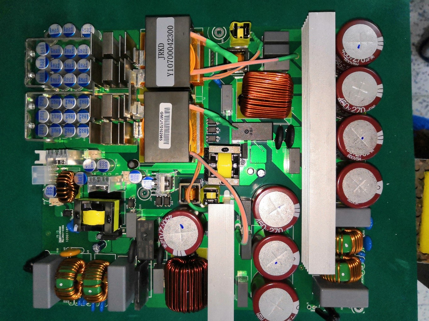
This figure is an actual picture. There may be small differences between different product versions, but the principle is similar.
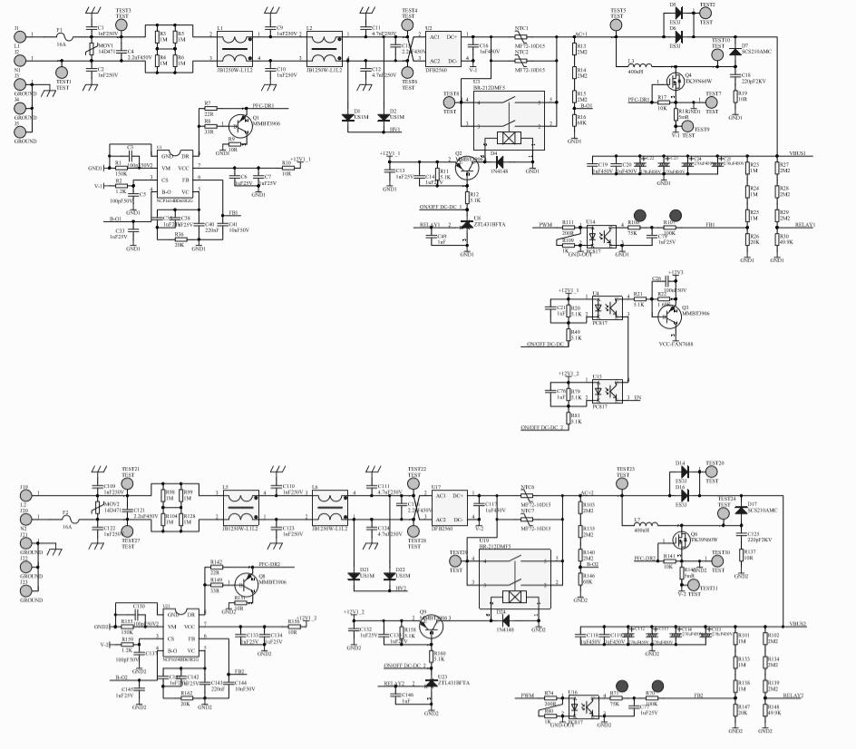
(1) Schematic diagram of two AC input EMI to PFC circuit, for example, for AC1 circuit, focus on measuring F1 insurance, U2 rectifier bridge, confirm whether Q4, D7, D5, D6 are damaged (the same inspection method as the other circuit). Note that when the MOS is damaged, the drive resistance and circuit may be damaged simultaneously and need to be replaced. During normal operation, it can be judged that the DC voltage across the large capacitor is 410 420V.
(2) Two 12V auxiliary circuits and fan power supply principles, for example, for 12V 1 channel, focus on measuring the voltage to detect the starting resistance R33, 47K and confirm the HV is connected to D1, D2, check whether F3, Q5, D8, D9, T1 are damaged, etc. (the same inspection method as the other circuit). 12V output. The following circuit converts the front end two 12V series to the output terminal + 12V for the miner control board.
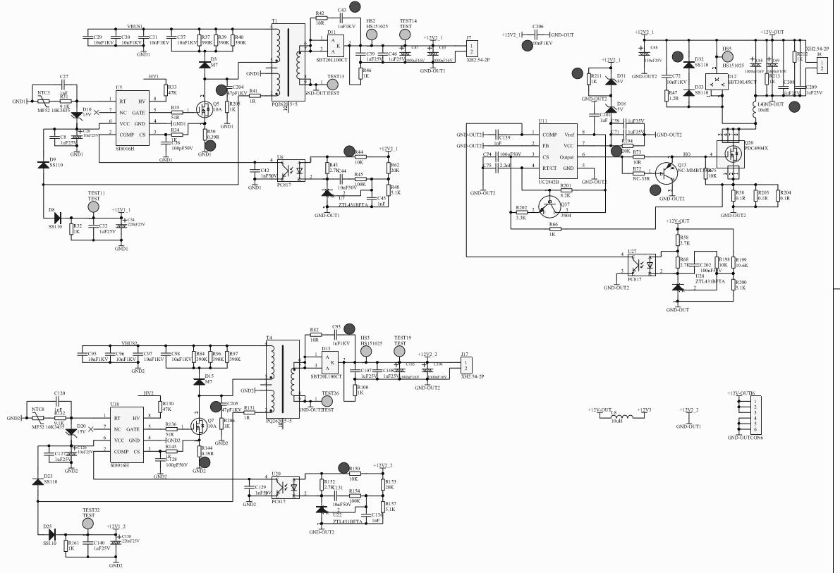
Main PWM chip U9 VCC power supply control. Note that the front two circuits PFCs need to work properly.
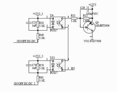
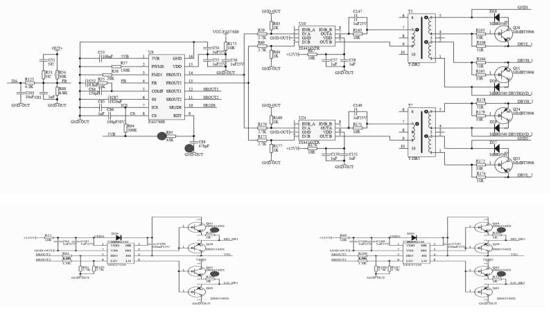
(3) Main control PWM drive circuit, PIC control voltage regulation principle diagram, focusing on measuring the main IC VCC power supply and driving transformer.
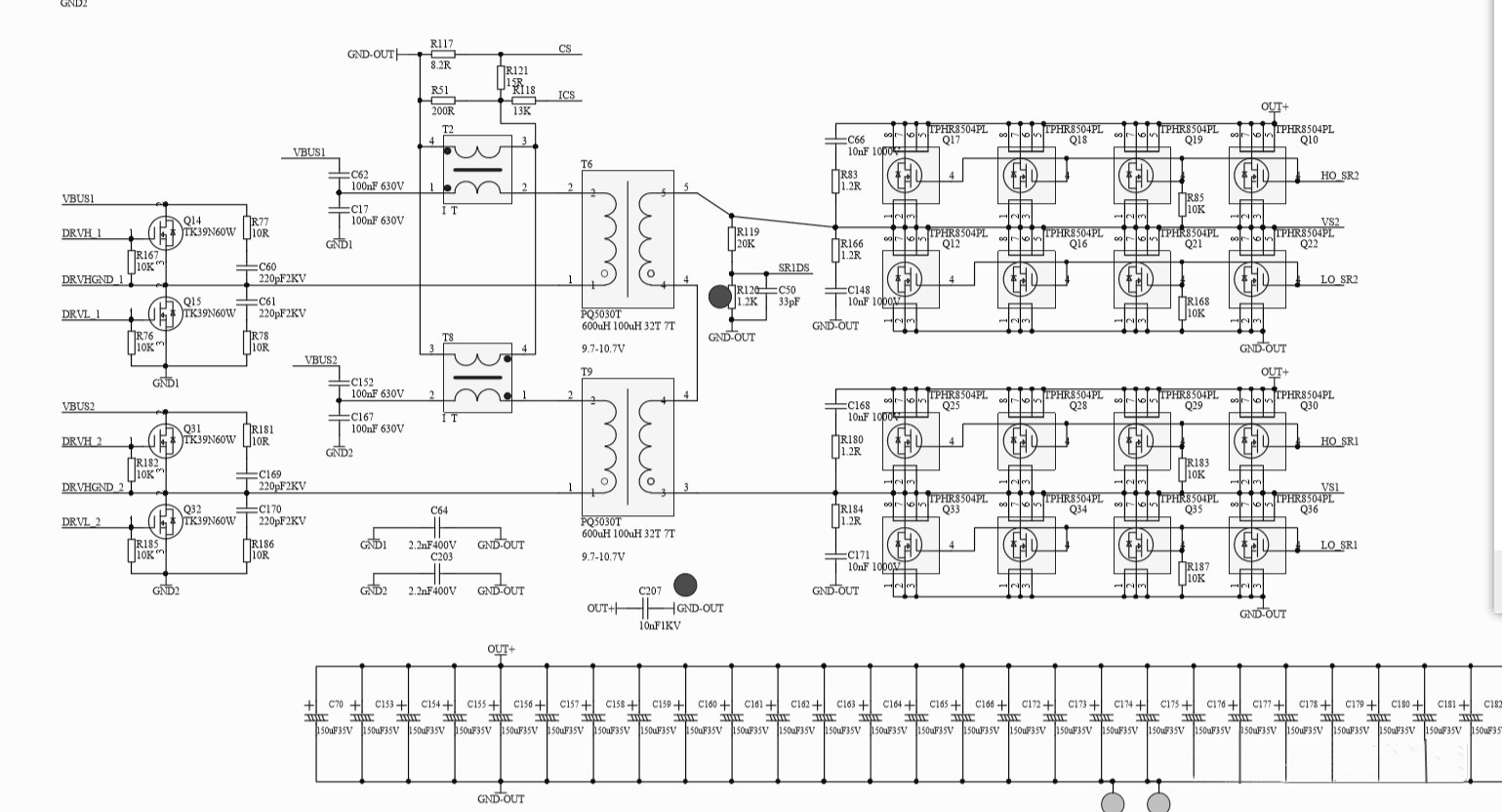
(4) LLC circuit two main switch MOS and transformer conversion voltage-reduction synchronous rectification DC filter output circuit, focusing on testing the main switch MOS Q14; Q15; Q31; Q32, check whether there is a short circuit phenomenon at the positive and negative pole of the output rectifier chip MOS, over-current protection circuit transformer, etc.
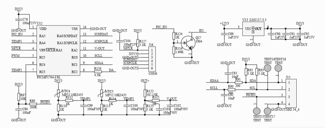
(5) PIC control circuit, J15 communication and programming port.
(6) SMD paster A side and plug-in B side device position silk screen.

3. Maintenance process
(1) Check whether the appearance of the power supply is seriously damaged or deformed, and whether the DC fan and AC outlet are damaged.
(2) Power on AC220V and check whether the fan is rotating normally. Use a multimeter to measures and check whether the output voltage of the J6 terminal is 12V (12.1V-12.50).
(3) Open the shell and check the components and soldering surface for sparking and scorching (focus on whether D1 D2, D21 and D22 are damaged, and whether 12V circuit chip capacitors are burning), use a multimeter to detect whether the AC input F1 fuse is open circuit, check U2 rectifier bridge and PFC MOS Q4; D7; D5; D6 to confirm whether there is short circuit (the same inspection method as the other circuit), measure the main switch of PWM circuit MOS Q31; Q32; Q15; Q16 and output chip MOS Q17; Q18; Q19 ; Q20; check whether there is a short circuit. If there is a short circuit, operator needs to check and replace the component position. Pay attention to the circuit resistance around the bad bit MOS tube; the transistor may be damaged and need to be replaced.
(4) Check whether the auxiliary 12V circuit F3, U5; T1; Q5; D8, D9 and other components have short circuit or open circuit phenomenon and whether the surrounding components are burned, etc., if necessary, replace them.
(5) If there is no abnormality in the above position, the F1 or F2 fuse circuit is normal, and the DC fan rotates after the two AC circuits are powered on (if it doesn't rotate, please measure whether the fan socket is 12V; if it rotates normally, the fan shall be replaced normally), the output J6 is under 12V voltage. Measure and check whether there are DC410V-420V between the two ends of the two PFC large capacitance TEST20-TEST30 or TEST2-TEST7 measurement points, otherwise check the PFC chip U21 or U1, check the 7-pin VCC power supply has 12V or judge the material to be damaged and replace; if there is no abnormality, the PWM needs to be detected for circuit U9; U10; U24; power supply VCC has a voltage of 12V or judges that the material is damaged and replaced, and whether the T5 or T7 drive transformer is damaged.
(6) Other defects need to be further analyzed and judged according to the skills of the maintenance personnel.
After the above inspections are completed, the main DC output of the single power supply test needs to be about DC21.3V after short circuiting the J15 PIN pin 4-5 pins, as shown in the EN- GND pin. Note that the short circuit error may damage the chip. Only after the replacement of the defective device is checked and the welding is correct, can the AC220V test be performed. Note: If other circuits are checked that the normal large capacitor is 420V, and there is no output after short- circuiting, it can also be judged that the PIC chip U12 firmware is reprogrammed or the IC is burned (generally there are fewer defects).

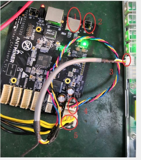
4. Available control board V1.2 and APW9 + power PIC port connection test chart.
Mark 1 is dedicated card test firmware;
Mark 2 is DC voltage debugging high and low conversion button;
Mark 3 is PIC communication port;
Mark 4 is control board letter socket;
Mark 5 is 12V power supply;
Please note that the yellow indicates positive and black indicates negative. Note: After the general power supply defective products are repaired, power on and short-circuit the PIC communication J15 port EN- GND pin, if there is a voltage output of about 21V as normal, it can be judged as normal and the control board test is not required (when the PIC microcontroller is broken, or the firmware is reprogrammed, then a small board test is required), and the corresponding miner can be directly installed for testing. After the power supply is repaired, if the current under 12V with a load is 12A, and current of the main voltage DC21V with a load if 170A, it is qualified.
5. Simple judgment and maintenance of common faults in mine power supply.
AC input corresponding to the fan, P1-F1; P2 --- F2; the first two groups work normally, P0 output to the fan corresponding to 12V.
| No. | Fault | Reason | Solution |
| 1 | The fan is not running and there is no 12V output | Power supply on AC side is abnormal | 1.Check whether the AC input of the power supply is normal and the plugs on both ends are not loose; 2. Check whether the power grid and the voltage is normal |
| 2 | The fan is running normally, no 12V output | 1.The grid voltage is too low; 2. Power protection | 1.Use a multimeter to confirm that the current voltage is above 205V, so as to ensure that the power supply is turned on;2.Check whether the power supply has an output short circuit or overload phenomenon. In case of this situation, put the clerk into the locked protection state. After troubleshooting, power on then it will be restored |
| 3 | After the power supply stops outputting for a few seconds, it resumes normal operation, and after a few minutes of operation, it stops outputting again and again. | Power supply is in temperature protection mode | 1.Check whether the fan is running normally; 2. Check whether the cooling duct of the power supply is blocked; 3. Check whether the power supply has been used for a long time, and there is too much internal dust; 4. Check the power used by the power supply or the ambient temperature exceeds the power limit value |
| 4 | The output is normal, the fan is not running | Damaged fan | 1.Check if the fan is blocked by debris; 2. The fan is broken |
| 5 | The normally working power supply suddenly has no output and will not start again | Power supply enters overcurrent protection mode | Check whether the current of the load exceeds the overcurrent protection of the power supply instantaneously. Set the power supply overcurrent protection to a locked state to prevent the power supply from continuously outputting, thus avoid causing fire and other dangerous situations when the load is abnormal |
6. After the maintenance test of the whole power supply is normal, it needs to operate for aging under more than 80% (140AA) of the rated load for 2 hours, and if it's qualified, it can be used by the client.
We use cookles to Improve your online experience. By continuing browsing this website, we assume you agree our use of cookies.