


ZEUS MINING has organized and updated the latest manual of the Innosilicon A11 series miner maintenance guide, which can help the maintenance personnel to quickly troubleshoot and repair the fault of the A11 series miner hash board.
Ⅰ. Introduction of A11 series miner models
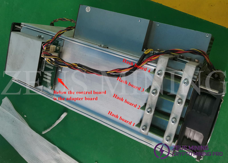
A11 series miner models, in terms of assembly, have two obvious differences with other models, please refer to the following figure:
1. From left to right, the hash board is Hashboard 1---Hashboard 4;
2. There is no SPI cable, the A11 series control board and the hash board are connected through the adapter board.
There are currently 6 types of models:
A11 Samsung particle, there are 8G and 16G;
A11M Magnesium Particles, 16G;
A11MX Magnesium Particles, 8G;
A8P is equivalent to A11
A8PM is equivalent to A11M
A8PMX is equivalent to A11MX
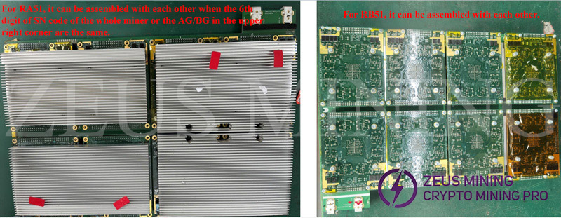
Due to the different DDR particles (brand, particle capacity), each model cannot be assembled at will!
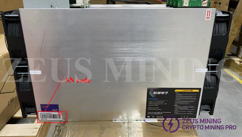
It is not recommended to mix hash boards / hash modules until you understand the machine properties. The premise of assembling the hash boards / hash modules is that the SN code information pasted on the barrel of the whole miner is consistent.
There are two types of SN code information:
RA51: such as RA51A21A2400441
RB51: such as RB51XN21C090704
The mutual assemble principle of the RB51 SN code:
1. They can be directly assemble with each other;
The mutual assemble principle of the RA51 SN code:
1. The sixth digit of SN code must be the same;
2. Both are AG or both are BG;
3. For A11M miners, those produced in 21 and 22 cannot be mixed (Look the 7th and 8th of SN code).
Ⅱ. Construction of repair platform
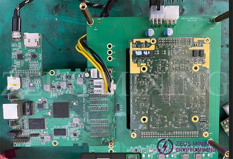
The repair platform used to repair the A11 hash board needs to use the A11 control board whose repair program has been burned into the control board (the repair program is divided into Samsung RA51 and magnesium RB51, and each repair post is equipped with 2 repair-specific control boards) , and the power board for single-module testing, or the power board of the A11 itself, use the power supply of the A11 itself or a 12V constant voltage power supply. The repair platform is built as follows:
Ⅲ. Troubleshooting of faulty miners
Taking the maintenance of the faulty miner as an example, the repair steps are as follows:
1. Before powering on, you need to use the buzzer gear of the UT890D+ multimeter to detect whether there is a short circuit fault at the power supply end of the hash board;
2. If there is a short circuit in the hash board, you need to disconnect the hash board and the power supply, measure the hash board separately, and find the short-circuited hash board;
3. First observe whether the appearance of the short-circuit hash board is defective, and then remove each hash board module one by one until the short-circuit hash board module is found;
4. If there is no short circuit, you can power on the whole miner, plug in the internet cable, scan the miner operation status and error information (refer to the picture below for the error code), and locate the faulty hash board;
5. Shut down the miner, take out the faulty hash board, visually inspect and locate the faulty hash board module, or test the faulty hash board by using the repair platform / using the barrel + test control board (refer to the figure below) (the method is similar to the repair of T3 + hash board), according to the error message from the repair platform, remove the faulty hash module and prepare for maintenance.

| Error code | Error type | Corresponds to the original error | Illustrate | Judgment basis | Repair advice |
| E0 | Visual inspection abnormality | F15 | Other | Other abnormal | |
| E1 | Visual inspection abnormality | F1 | Power supply abnormal | The control board and fan are not powered after the miner is power on | |
| E2 | Visual inspection abnormality | F7/F8/F12 | Control board abnormal | 1. Unable to burn 2. The Normal indicator on the control board does not flash after startup 3. The network port light does not flash after startup 4. IPSET button is invalid 5. Other control board failures | |
| E3 | Visual inspection abnormality | F2 | Network cannot be connected | Miner cannot report IP | |
| E4 | Visual inspection abnormality | F3 | Aging system does not show | Corresponding SLOT is not displayed on the aging system page | |
| 21 | Miner error code | 21 | 1 or more hashboards not detected | Error code is displayed in the ErrCode column of the aging system | |
| 22 | Miner error code | 22 | The I2C communication of power supply is abnormal | Error code is displayed in the ErrCode column of the aging system | |
| 23 | Miner error code | 23 | All hash boards' SPI chains fail | Error code is displayed in the ErrCode column of the aging system | |
| 24 | Miner error code | 24 | The SPI chain of some hash boards fail | Error code is displayed in the ErrCode column of the aging system | Overhaul craft, SPI cable, etc. |
| 25 | Miner error code | 25 | Overclocking failed | Error code is displayed in the ErrCode column of the aging system | |
| 26 | Miner error code | 26 | Failed to set voltage | Error code is displayed in the ErrCode column of the aging system | A11 report 26 is SPI communication problem |
| 27 | Miner error code | 27 | bist failed | Error code is displayed in the ErrCode column of the aging system | |
| 28 | Miner error code | 28 | SPI error at runtime and no automatic recovery | Error code is displayed in the ErrCode column of the aging system | |
| 29 | Miner error code | 29 | Error in I2C communication at runtime and no automatic recovery | Error code is displayed in the ErrCode column of the aging system | |
| 30 | Miner error code | 30 | Connection to the mining pool is interrupted | Error code is displayed in the ErrCode column of the aging system | |
| 31 | Miner error code | 31 | Damage to individual chips leads to inflated hashrate | Error code is displayed in the ErrCode column of the aging system | |
| 32 | Miner error code | 32 | Temperature is too high | Error code is displayed in the ErrCode column of the aging system | |
| 33 | Miner error code | 33 | Failed to read temperature (error in SPI communication during runtime) | Error code is displayed in the ErrCode column of the aging system | A11 series power off and restart is still invalid, replace the control module |
| 34 | Miner error code | 34 | SPI cable connection is abnormal | Error code is displayed in the ErrCode column of the aging system | |
| 35 | Miner error code | 35 | Power supply abnormal | Error code is displayed in the ErrCode column of the aging system | |
| 36 | Miner error code | 36 | Number of good cores in the chip is abnormal | Error code is displayed in the ErrCode column of the aging system | |
| 37 | Miner error code | 37 | Control board's vid type error | Error code is displayed in the ErrCode column of the aging system | |
| 40 | Miner error code | None | Insufficient power load | Error code is displayed in the ErrCode column of the aging system | |
| 41 | Miner error code | None | Power supply startup voltage is too low | Error code is displayed in the ErrCode column of the aging system | |
| 42 | Miner error code | None | Overclocking fails and cannot be automatically recovered | Error code is displayed in the ErrCode column of the aging system | |
| 43 | Miner error code | None | A certain level of chip voltage is abnormal | Error code is displayed in the ErrCode column of the aging system | |
| 44 | Miner error code | None | Hash board A/B pressure difference is too high | Error code is displayed in the ErrCode column of the aging system | |
| 46 | Miner error code | None | Control board test mode on | Error code is displayed in the ErrCode column of the aging system | |
| 47 | Miner error code | None | Overtemperature protection fails (software defect) | Error code is displayed in the ErrCode column of the aging system | |
| 48 | Miner error code | None | Local temperature of the hash board is too high | Error code is displayed in the ErrCode column of the aging system | |
| 49 | Miner error code | None | Power supply model does not match the miner model | Error code is displayed in the ErrCode column of the aging system | |
| 50 | Miner error code | None | Control board SPI HUB register detection error | Error code is displayed in the ErrCode column of the aging system | |
| 51 | Miner error code | 28 | Failed to read voltage after switching to SPI 3M | Error code is displayed in the ErrCode column of the aging system | |
| 52 | Miner error code | None | Aging frequency parameter is less than 600M | Error code is displayed in the ErrCode column of the aging system | |
| 53 | Miner error code | None | Aging frequency parameter of a certain chain is abnormal | Error code is displayed in the ErrCode column of the aging system | |
| 55 | Miner error code | None | A11 GDDR is at low speed | Error code is displayed in the ErrCode column of the aging system | |
| 56 | Miner error code | None | A11 3G rate configuration failed | Error code is displayed in the ErrCode column of the aging system | |
| 57 | Miner error code | None | Abnormal power consumption parameters of the power supply | Error code is displayed in the ErrCode column of the aging system | |
| 59 | Miner error code | None | ddr particle initialization failed | Error code is displayed in the ErrCode column of the aging system | A11 series power off and restart is still invalid, replace the control module |
| 60 | Miner error code | None | A11 low frequency to high frequency failed | Error code is displayed in the ErrCode column of the aging system | A11 series power off and restart is still invalid, replace the control module |
| 61 | Miner error code | None | A11 Cache calculation error | Error code is displayed in the ErrCode column of the aging system | A11 series power off and restart is still invalid, replace the control module |
| 62 | Miner error code | None | A11 dag calculation error | Error code is displayed in the ErrCode column of the aging system | A11 series power off and restart is still invalid, replace the control module |
| 63 | Miner error code | None | A11 job calculation error | Error code is displayed in the ErrCode column of the aging system | A11 series power off and restart is still invalid, replace the control module |
| 64 | Miner error code | None | Average temperature of GDDR particles > 68℃ | Error code is displayed in the ErrCode column of the aging system | Check heat dissipation strips and heat sinks, fans |
| 65 | Miner error code | None | ASIC chip temperature>78℃ | Error code is displayed in the ErrCode column of the aging system | Check silicone grease and heat sinks, fans |
Ⅳ. Fault location and repair of hash module
1. Clean the dust on the surface and inside of the hash module in turn;
2. Visual inspection to see if there is corrosion or loss of capacitors, resistors, etc., and targeted repair;
3. Use the diode gear of the multimeter to measure the ground value of the 6 voltage points. Under normal temperature, the ground value of the hash module's VDD is not less than 1Ω, the ground value of VDDQ is not less than 20Ω, the ground value of U3/U4/U6/U7's output terminal are open circuit (the value of the diode measured in the diode gear is not lower than 0.10v, as shown in the lower right figure), otherwise there may be a short circuit, and the short circuit must be eliminated before powering on.
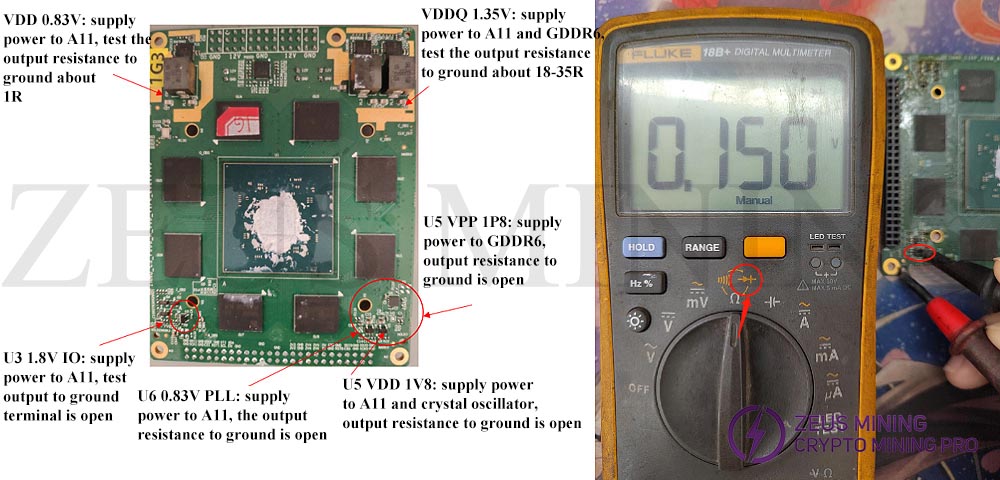
4. After confirming that there is no short circuit, install the hash module to be repaired on the single-module power supply board, power on and test, and measure the output of the 6 voltage points (as shown in the upper left), with the help of the repair test program (refer to the test page below figure) to locate the fault point and carry out maintenance (Note: the hash module cannot be powered on for a long time without a heat sink).
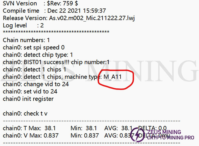
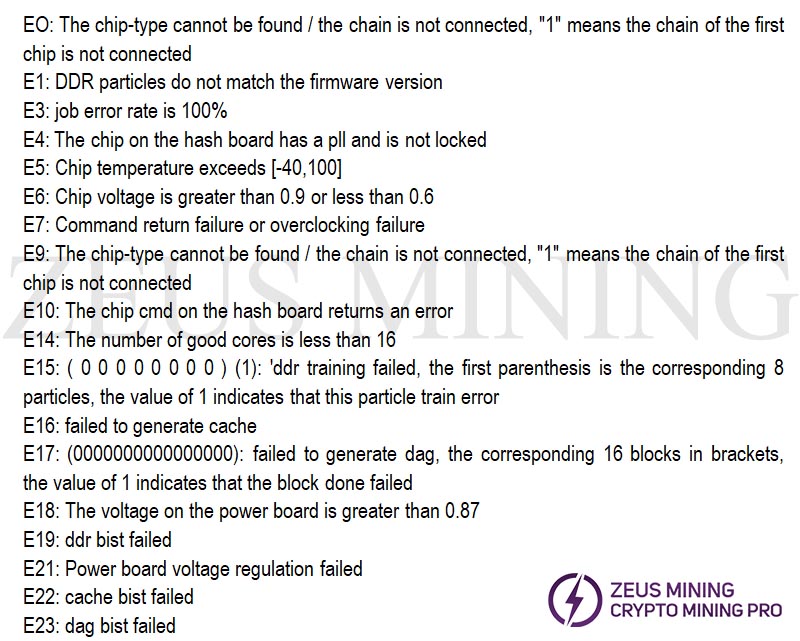
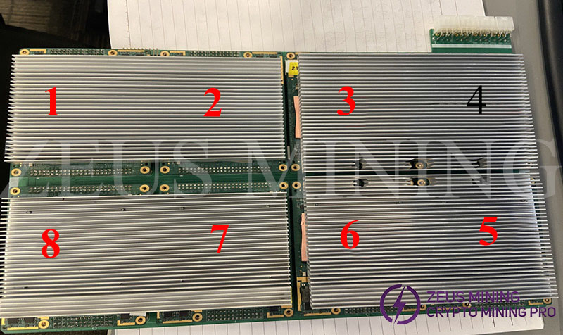
(1) If the chain fails, an error E0 will be reported, followed by the wrong module number. There are 8 hashboard modules on each board as shown in the figure below. The board test locates the specific module problem and removes the module for maintenance. Most of the faults are caused by the failure of the chain, which may be caused by the adapter board or the corrosion of the module. Only the repair of E0 is listed below. Other error codes are not recommended to be repaired by yourself.
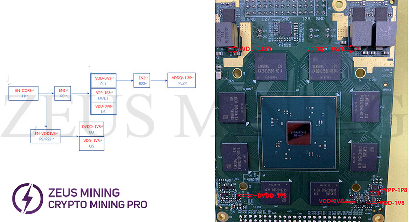
(2) Timing diagram of module voltage (referring to which voltage comes first and then which voltage), refer to the following diagram for repair in order to ensure that the voltage is all right.
Ⅴ. Common problems
1. Fauty problem due to corrosion
The common problem of A11 series miners is the failure caused by corrosion. The modules, power boards and adapter boards near the air inlet have a high probability of failure.
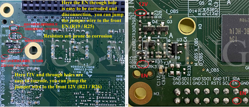
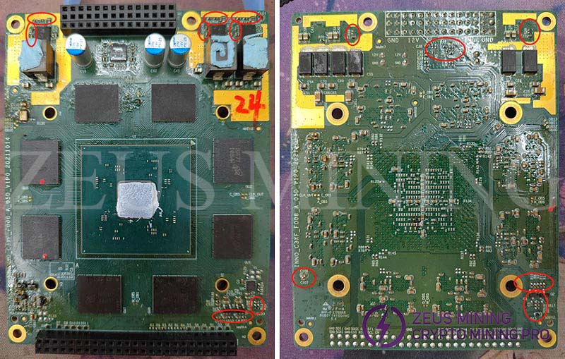
Corroded capacitors, resistors, etc. need to be cleaned up, scraped off the oxide layer with a blade, then re-tinned the pads, soldered new components, and coated with the three-anti-glue.The same position of other modules of the air inlet also needs to be checked for corrosion, if necessary, replace the new components, and then apply the three-anti-glue.
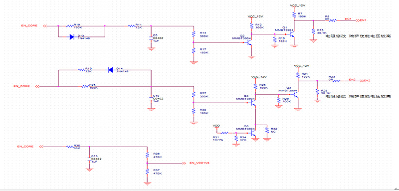
(1) The computing power module is corroded and disconnected;
(2) Corrosion and disconnection of the power board;
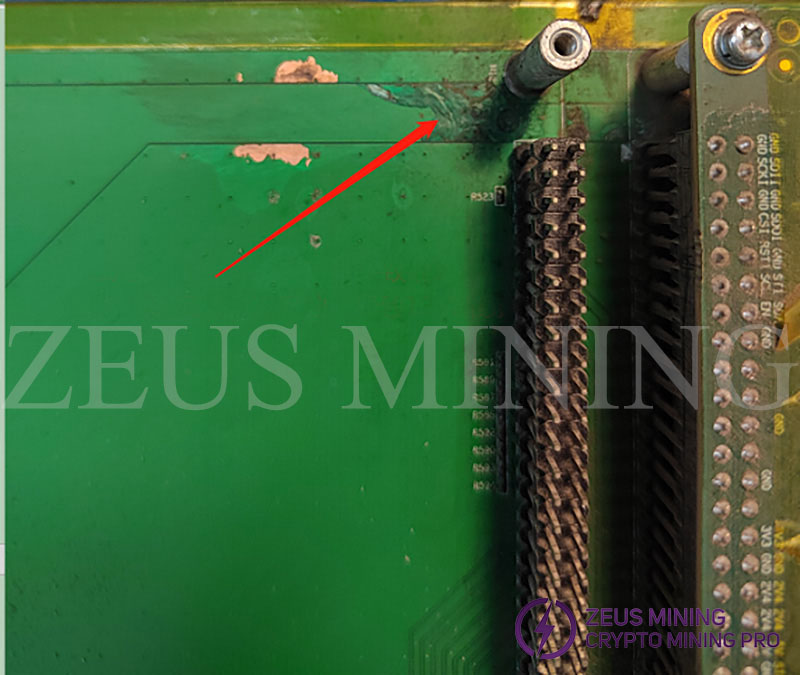
For a hash board module with corrosion phenomenon, there is a high probability that one or more of the 6 output voltages have problems. Carefully observe the corrosion point or refer to the timing diagram to find the problem point. After finding the disconnection position, refer to the following circuit diagram to jump wire.
2. The adapter board is faulty
There are also many problems that are prone to occur with the adapter board:
(1) circuit corrosion;
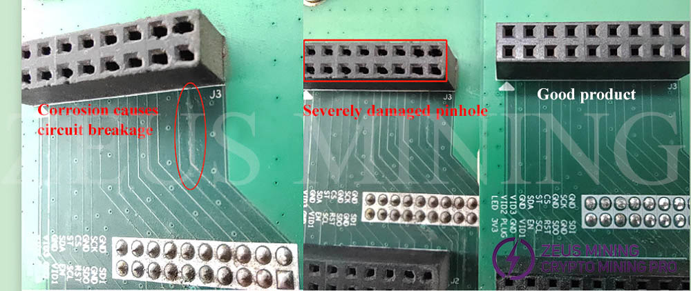
(2) The adapter board's socket is damaged;
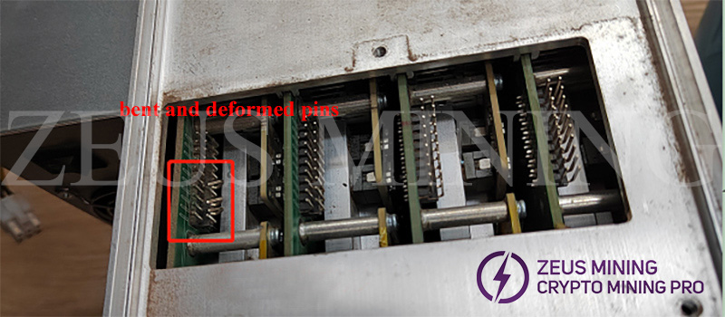
(3) Poor contact of the adapter board;
When the adapter board and the hash board are assembled, the alignment of the pins and sockets cannot be seen intuitively, and there are many pins, deviations in the alignment, and brute force installation will cause the pins to be deformed, dislocated, or even damaged.
Ⅵ. Precautions
1. The disassembly and installation of the adapter board must be gentle, and brute force should not be used.
When disassembling, you can pry it up little by little near the four corners of the adapter board, and pay attention to protect the pins of the SPI socket of the hash board.
When installing, first put the hash board into the miner barrel, push it to the bottom, and then check whether the pins of the SPI socket of the hash board are bent, make sure that there is no difference in the orientation and spacing of the pins, and finally place the adapter board lightly on the hash board. Just above the SPI socket of the force plate, make a slight adjustment to ensure that the plug pins are aligned with the jacks, and then press the adapter board lightly and firmly to connect the adapter board and the SPI socket in place. After checking that there is no problem with the installation, lock the electrode screws of the hash board;
2. When repairing the hash board or hash module, make sure that each voltage point is not short-circuited to ground before powering on;
3. If the hash module is not equipped with a heat sink, it should not be powered on for a long time to avoid overheating of the main chip and DDR;
4. For the hash module at the air inlet, a gray strip should be installed on the air inlet side, and the common corrosion-prone positions should be coated with three-anti-glue;
5. When testing the module that reports error E0, there is a high probability that the voltage output is abnormal due to corrosion. If the 6 voltage outputs are normal and stable, and the crystal oscillator is working normally, the fault of error E0 still cannot be solved. It is recommended to gather such modules that cannot be handled and send to professional repair center for repair;
6. When repairing a short-circuited module (usually PL1 / PL2 / PL3 is short-circuited to ground), if it is still short-circuited after removing PL1 / 2 / 3, such modules cannot be repaired on site and need to be sent to professional repair center for unified treatment;
7. There are two common types of the hash module: Samsung RA51 and Magnesium RB51. The repair program (referring to the repair-specific control board) must match the hash board / module to be tested, in order to complete the normal test and display the correct test results. If It is only necessary to verify whether the hash board / module to be tested is connected (whether an error E0 is reported), there is no requirement for the repair program, and the model of the miner / chip appears on the test program display page (you can see the monitored temperature and voltage on the page at this time).
8. For the hash module reporting error E3, if the voltage of the 6 voltage points is normal and stable, it can be regarded as a good module, install it as a complete miner and run it on the shelf to see if it can work normally;
9. For the module reporting error E4, focus on checking whether the crystal oscillator output is normal (use the DS1102E Oscilloscope to measure the crystal oscillator output waveform);
10. When the test result shows that the error E21 is reported, it is the power board failure. Check whether the resistor near the socket on the power board is abnormal;
11. Site maintenance point, it is only required to repair the normal faults of the module in question (only the module that reports the error E0 needs to be repaired). For other errors, or faults that cannot be repaired on site, mark the module's error message and send it to the professional repair site for repair.