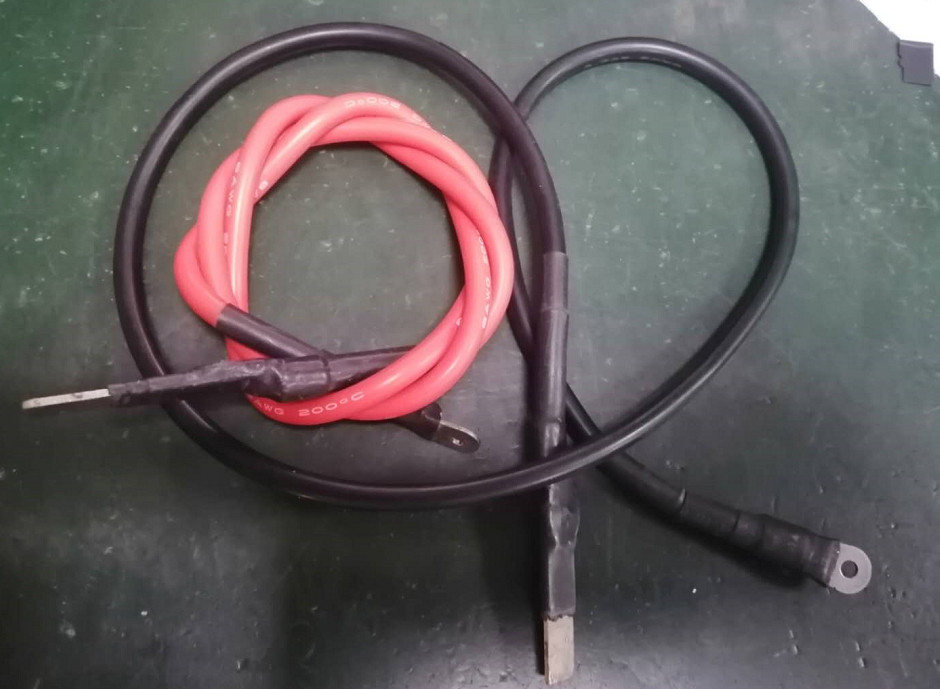


Welcome to the V9 V1.2 test fixture manual, this manual is suitable for the S9 series, S11, S15, T15, DR5, D5, S17, S17PRO, T17 miners. ZEUS MINING hopes it will help you.
1. Preparation
Platform: Computer (Windows system)
Tool: electric soldering iron (60W)
Fixture: hash board test fixture
Data line: 1 S9 data line
The voltage regulating wire: voltage regulating cable
Fans: 4 fans are required to test S17, S17PRO, and T17. Since there are only 2 fan ports on the fixture, you can choose to buy a fan with 1 to 2 connectors when using it, or use other power supplies to allow 4 fans to meet the heat dissipation requirements, and you need to dissipate up and down or side heat dissipation.
Power supply: It is recommended to use a 12V power supply, APW3, APW8, APW9 and other power supplies directly according to the needs of the test model, to avoid using the 12V adapter to test the current that will cause the fixture to cut off.
TF card: Burn the test program as required. Note: S15, T15, S17, S17PRO, T17, DR5, D5 need to transport the corresponding model master program to the fixture before testing usually.
USB to TTL port: CP210X series or TL43X series.
Dupont line: male and female 3P >30cm; generally, the serial port is also available.
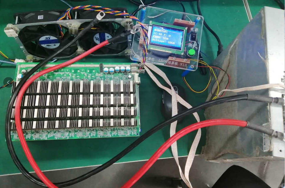
2. Hardware connection
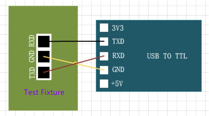
1) First, connect the serial port, the control board and the serial port board are connected as shown in the figure:
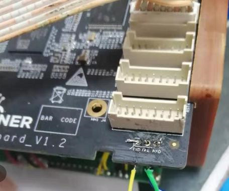
2) Weld the serial port board and connect the data cable. Note that the voltage regulator wire must be connected and powered on when the test fixture is started.
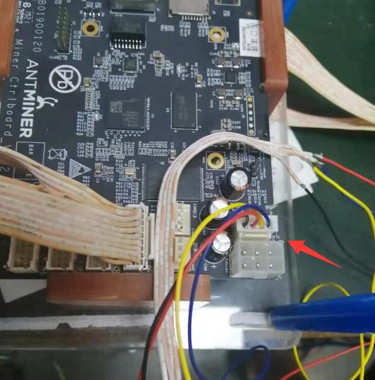
3) Connect the voltage regulating cable, and be careful not to plug it into the two side-by-side fan positions.
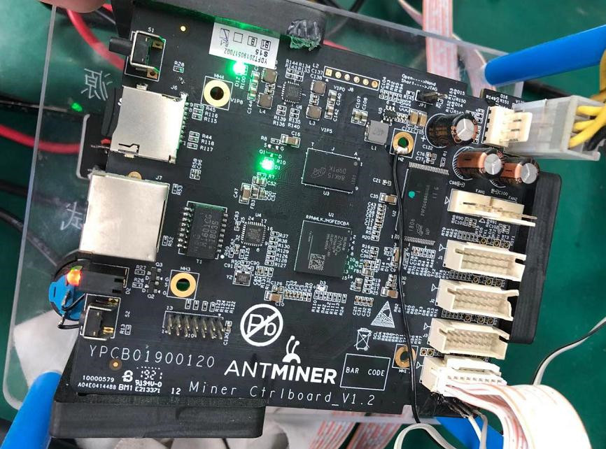
4) To transport the master chip of the test miner model.
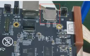
5) Insert the test TF card made corresponding to the model of the miner.
6) Plug in the power supply; the interface in Figure 1 below is the adapter power interface, which can directly plug into the power interface; if you use the APW3 power supply, you need to plug it into the 6PIN interface of the control board 2, but the power switch of the test fixture does not work.
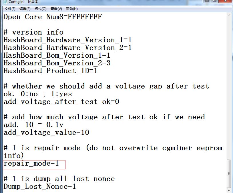
7) Configuration file description: repair=0, the test will cover the eeprom, and the whole machine needs to be re-scanned; repair=1, the test will not cover the eeprom data and does not affect the test and hash rate of the whole machine.
8) The legend is the start interface of the test fixture (for example, S17 and S17pro display interfaces are the same, and the single board test procedure is the same).
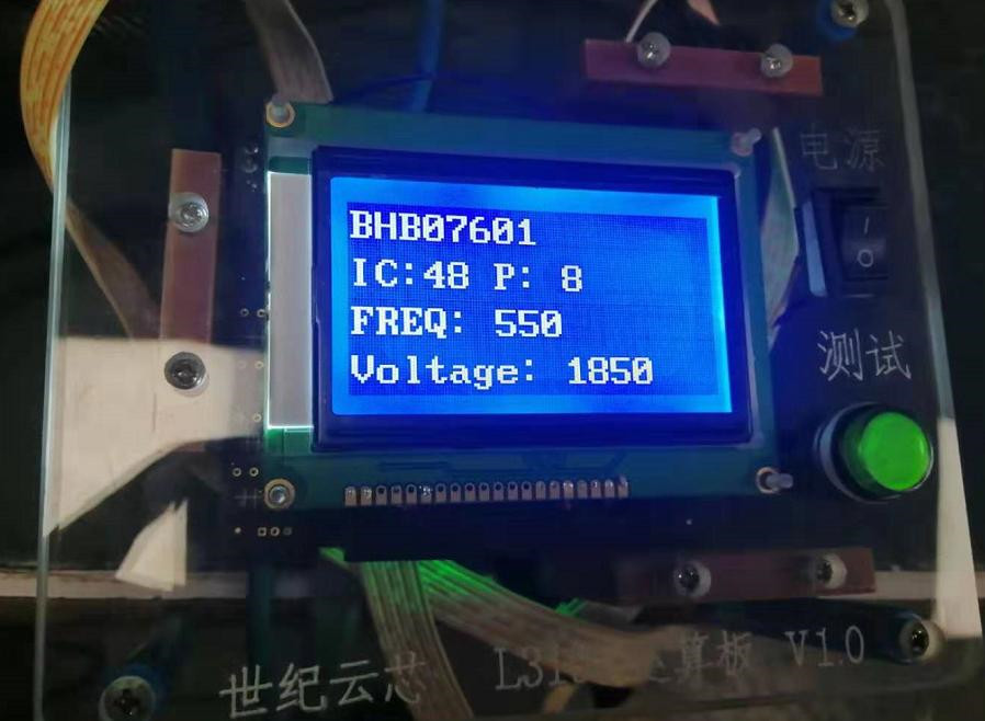
3. Matters needing attention
1) After testing the S17, S17PRO, and T17 models to detect the chip, because the temperature rises very fast after the chip is tested, four fans must be required to dissipate heat (You can refer to the picture for production. Note: Do not let the hash board come into contact with metal objects during the test, which may cause a short circuit).
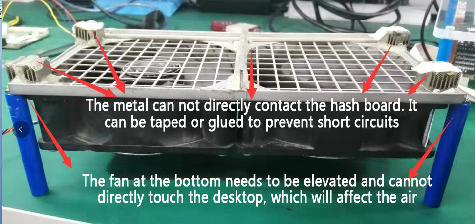
2) If all four fans cannot be plugged into the test fixture of the control board, the blue wire needs to be unplugged to let the fan run at high speed. Otherwise, it is easy to burn the board or chip; in addition, the heat sinks on the front and back of the hash board are charged. There should be no metal objects in contact with the hash board during the test to avoid damage to the chip or burn-in; the test results must all show OK. Otherwise, the whole machine test sweeps the frequency NG;
3) The voltage regulating line needs to be connected to the test power supply. When making an extension line, do not connect it randomly. If you are unclear, you can disconnect one by one to avoid errors;
4) To test different models, you need to carry the master program corresponding to the fixture (except for S9, S9i, S9j, T9+, and other models, you can use the universal package, and other models need to be transported);
5) The test fixture power supply cannot be the same as the test hash board. Otherwise, the test fixture will burn out quickly; if a 12V adapter is used, it must be 12V5A and above;
6) When using the V9 V1.2 version of the fixture, the tested power extension cord requires a line loss of less than 0.1V (below 100mV). For example, the power output is 18.5V, and the minimum voltage to the power interface of the hach board needs to reach 18.4V. When the power line loss voltage is more significant than 0.1V, it is easy to cause the single board PATTER NG;
7) S9K and S9SE need to configure the corresponding config and single-board-test files;
8) Customers need to make their copper axis (at least 6 square flexible wire) to connect the hash board, one end needs to be connected with APW8 or APW9 with a screw hole, and the other end needs to be clamped on the hash board (the joints need to be isolated by heat shrinkable tubing, as shown in the figure below Show).
