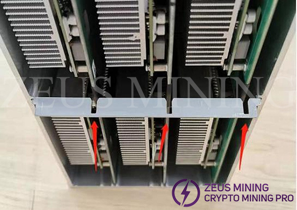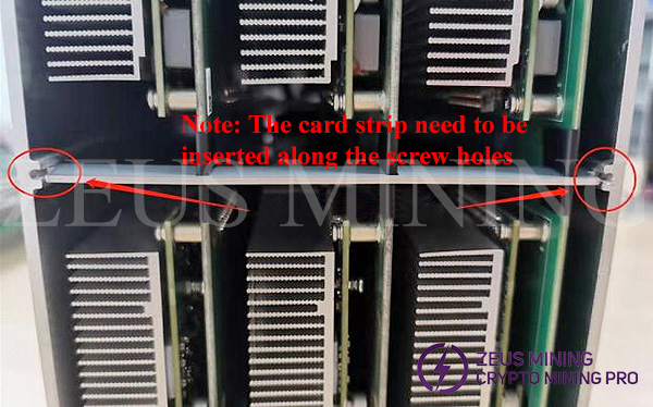


How do you properly dismantle the Innosilicon A10 miner and disassemble the faulty power board or hash module? The specific steps are as follows:
Disassembly tool: Phillips screwdriver. Of course, a portable electric screwdriver is more convenient.
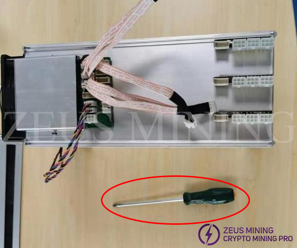
Specific disassembly steps:
1. Remove the power supply and unplug the data cables.
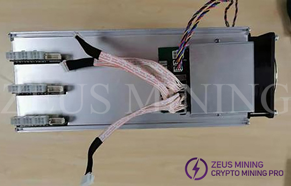
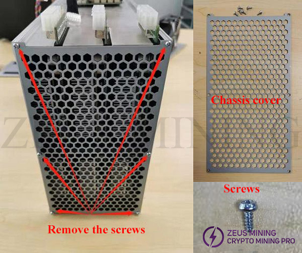
2. Remove the screws of the air outlet cover and remove the cover.
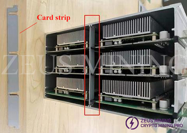
3. Pull out the limit clip
4. Unplug the power strip assembly that needs repair
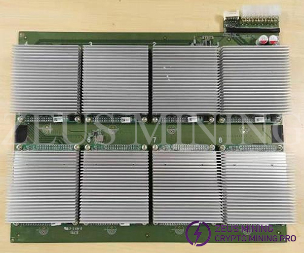
5. Remove the mechanical screws of the hash module that need to be repaired, and unplug the hash module part.
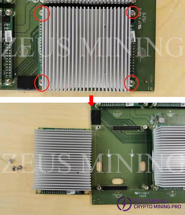
6. Remove the spring screws of the hash module, remove the heat sink, repair hash module, and the disassembly is completed.
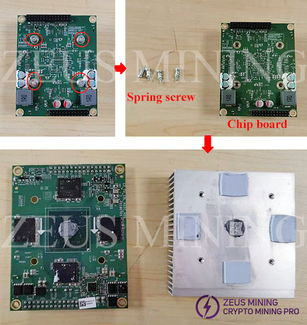
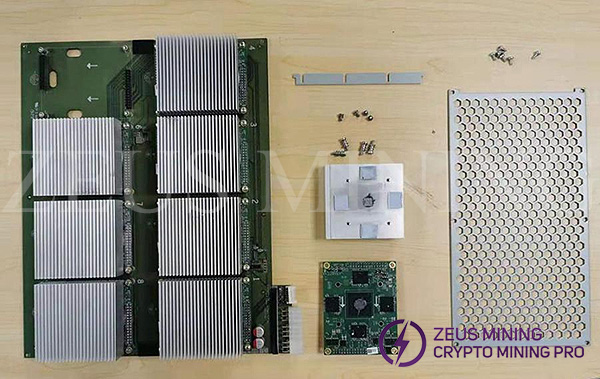
Precautions for repair and assembly the hash modules:
1. Attention methods for repairing 55/56 faulty miner chip board components:
1) For such problems, follow the disassembly steps to step 5. That is to say, there is no need to remove the small heat sink on the chip board.
2) First find a miner to disassemble, remove all the good small boards, and use this miner as a spare miner for bad small boards. Pay attention to anti-static.
3) Then find the defective miner that needs to be replaced, find the 55/56 defective small board and remove it, and then install the defective chip board assembly on the spare miner with the defective small board; at the same time, replace this miner with a good one chip board assembly. (The following chip board components are referred to as small boards)
4) Until the miner with defective small boards is filled with defective small boards. Repeat the same steps as above.
2. If it is on-site maintenance, it needs to be disassembled to step 6.
Installation precautions
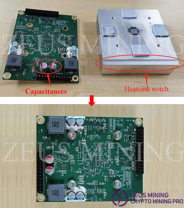
1. The installation and placement of the chip board is as shown in the figure: the two high plug-in capacitors need to be aligned with the gap of the heat sink, just above the gap, and then aligned with the screw holes after placement, and then lock the screws.
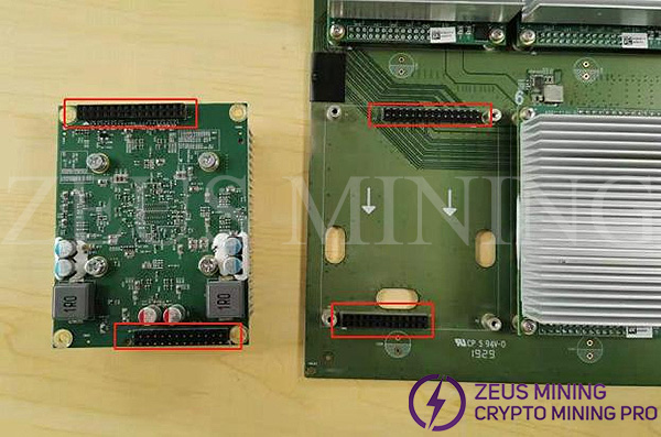
2. Reinstall the chip board to the power board: Align the chip board and install it on the power board, pay attention to the direction, and cannot be installed in the reverse direction;
3. Install the power board into the chassis, install the limit clips, pay attention to the one-to-one correspondence between the notch and the power board, and insert them along the screw holes; finally install the cover plate, lock the cover plate screws, complete the assembly, and put it on the shelf.
